Sprint 3
For Sprint 3, our goal was to reach our minimal viable product (MVP), a robot that follows a person on flat ground. To achieve this goal, we needed to accomplish full integration of all the mechanical, electrical, and software subsystems. The mechanical subsystem had a personal goal of having a finalized mechanical system, so the final sprint could be focused on fine-tuning the robot.
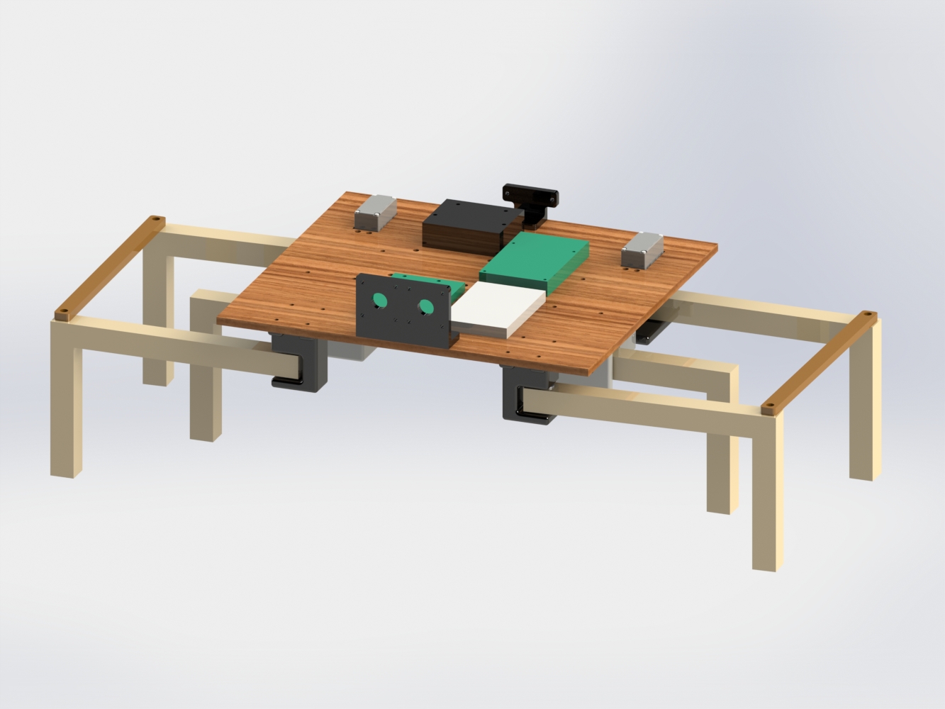
The overall mechanical design of the robot was very similar to the Sprint 2 design. However, there were many changes made to the structure of the robot. To make the robot more crab-like, we changed the dimensions of the legs so they would extend out further from the body of the robot while being the same distance from the ground, thereby having dimensions closer to those of crab legs. The changes in the legs also allowed the robot to have a longer stride, making it faster. In this sprint, we also redesigned the chassis so we would be able to bolt down our electrical components. In the last sprint, we taped the breadboard and Arduino to the chassis and the legs were screwed into the board. To make all the components on the chassis secure, we laser cut the chassis to include bolt holes for all the components (legs, Arduino, breadboard, Raspberry Pi, step down power supply, and battery). It was a difficult task to make sure that none of the components conflicted, but were able to solve the puzzle efficiently.
For the robot to look more professional, we improved our fabrication materials. In the previous sprints, we 3-D printed most of our parts or used cheap materials found in the stock market at the shop. This sprint, we used plywood for the legs and chassis, laser cutting the chassis and shopbotting the legs.
To help the robot lift itself, we add the new servos to the robot. These servos are very strong and are easily able to raise the robot off the ground.
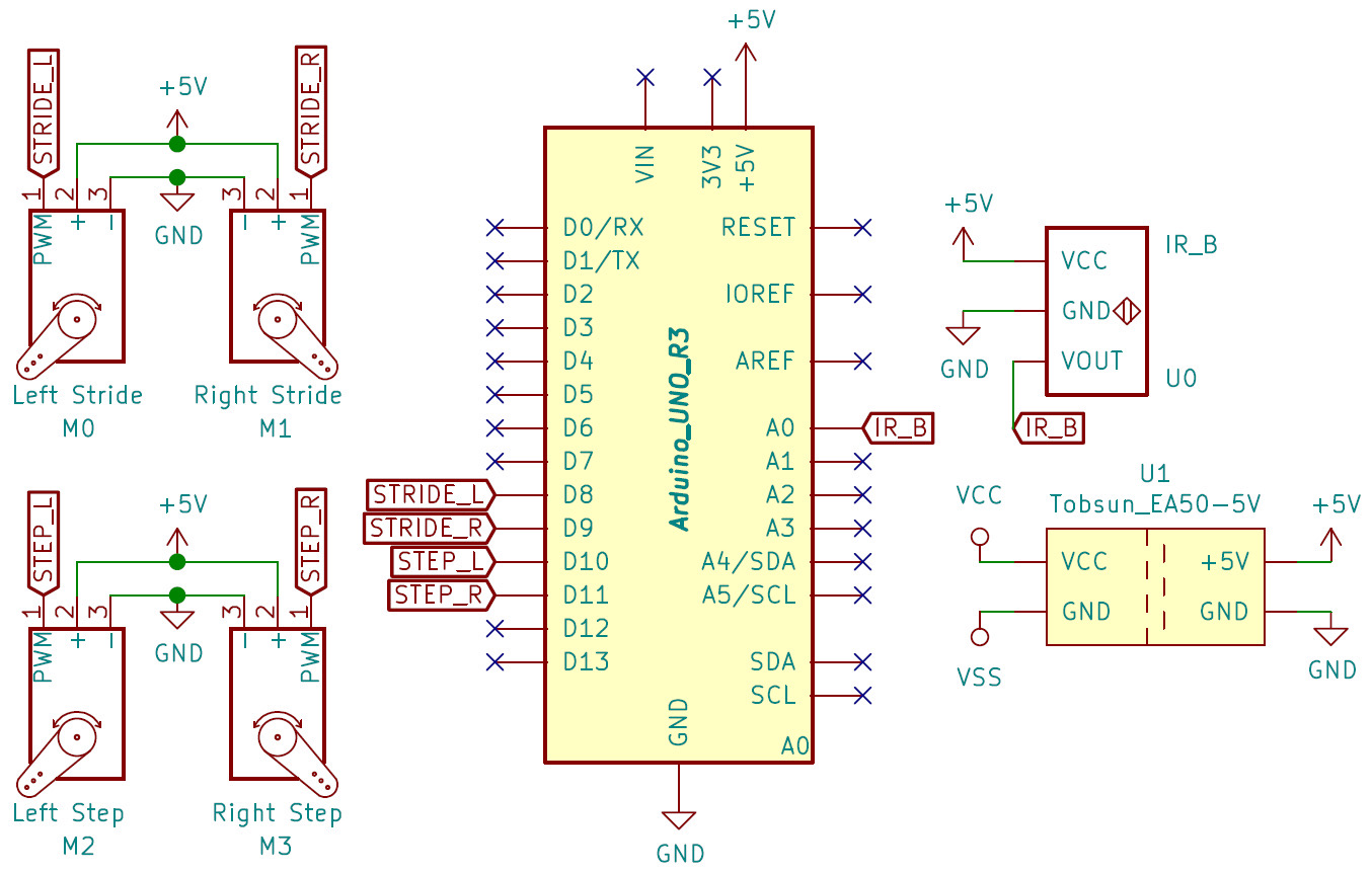
To make the robot wireless, we connected our robot to a lipo battery. The battery runs at 14.8V 1550mAh, which is more than enough power than is needed for the Raspberry Pi and the Arduino. As a result, we decided to invest in a step down power supply. The step down regulates the incoming voltage and current from the battery to a usable voltage and current for the Arduino and Raspberry Pi. To power both parts from the battery, we created a cable that splits into two plugs, one connecting to the Arduino to power and the other connecting to the Raspberry Pi. All the other electrical components are connected the same way as they were in Sprint 2.
Once all the components were connected to the battery, we tested the robot. The first time the battery was connected to the step down power supply, nothing worked. After a simple investigation, we learned that we wired the plug for the Raspberry Pi incorrectly. We switched the power and ground wires, luckily not frying the Raspberry Pi. After that problem was solved, we tried testing again and it began to walk. However, after the robot took its first step, it fell backwards. This was due to the weight not being evenly distributed on the chassis, with the majority of the weight being on the backside. To correct this problem, we decided to move the heaviest component, the battery, towards the front of the robot. As a result, we had to unscrew some of the other components from the chassis to make room for the battery. Then, we tested the robot again and it walked with no problems.
We did not successfully complete all of our goals for Sprint 3. We were unable to integrate the computer vision, the software in charge of tracking a person, with the assembled mechanical and electrical systems.
During this sprint, we learned which components we need to focus on to achieve our goals for our final product. These goals are as follows:
- Integrate a path planning algorithm.
- Tidy and organize the electrical system.
- Redesign the chassis to hold components and so there is generally less wobble.
- Design the robot to look more like a crab.
- Increase traction for the legs - make rubber feet.