Mechanical
Lateral Legs
The lateral leg system allows the robot to stride forwards. The system has a front and rear leg with a hobby servo motor attached to the rear leg, powering the system. They are connected via a 4 bar linkage with a connecting bar across one side and the chassis as the fourth link. There is one lateral leg system on each side of the robot that are mirrors of each other.
The lateral legs are built out of plywood and fabricated out of ¾” plywood using the shopbot. They are 5” tall and extend 8” from the chassis to give the robot a large stride length and increase its speed. There are small rubber squares on the bottom of each foot to add traction when the robot is on flat ground and maximize its speed without slipping. The cross bar is laser cut ¼” plywood and connects the “knees” of the front and rear legs. The other ends of the legs are attached to mounting brackets that connect them to the chassis. The rear bracket also holds the servo motor and both the bracket and the servo are bolted to the chassis. The lateral leg system works by moving the legs back and forth, but they are only in contact with the ground on the forward stride because of the movement of the vertical legs.
The connections between links in the system are ¼-20 bolts that screw into one link and float freely in the other, allowing them to pivot easily but still be laterally constrained. To reduce friction in the system, there are metal washers in between the wooden legs and the brackets on their axes.
Vertical Legs
The vertical leg system lifts one side of the robot up while the corresponding lateral leg system resets to the beginning of its step, which allows the robot to move forwards, as opposed to just shifting back and forth. We used more powerful servo motors for the vertical leg system because it has to lift about half of the full weight of the robot instead of just propelling it forward. The middle leg is also made of shopbotted ¾” plywood and extends 5” laterally instead of the 8” that the lateral legs extend, preventing interference. The middle leg is bolted to the servo horn which is screwed into the motor. Additionally, the shaft is supported on the opposite side from the servo by a ¼-20 bolt that goes through the leg mount.
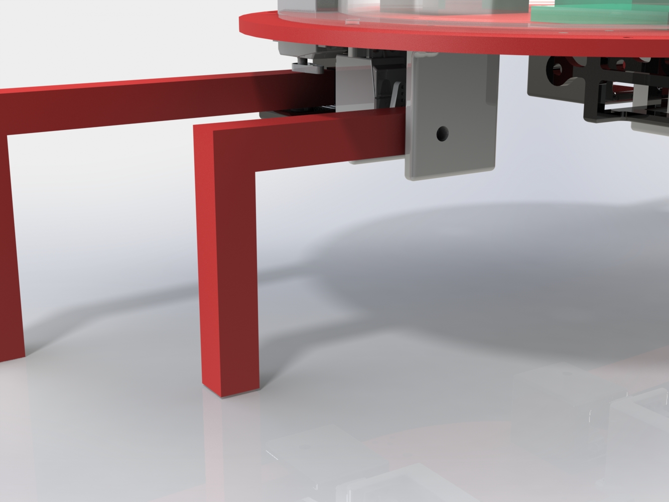
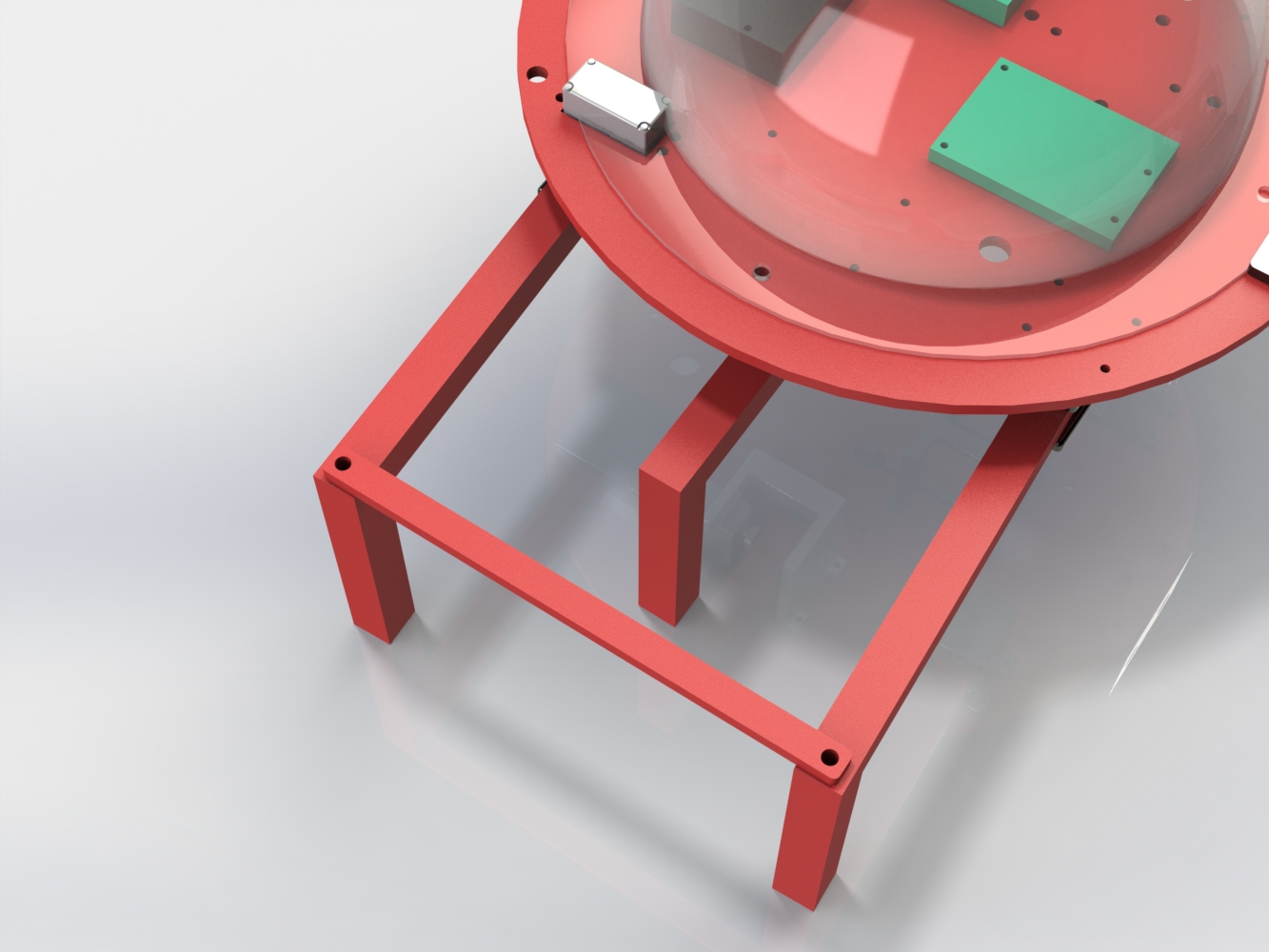
Chassis and organization
Our final chassis was designed as a circle and painted red to create a ladybug aesthetic. On the front there is a mount for the two cameras, and they are set to look like eyes. The Arduino and Raspberry Pi are both bolted to the chassis with spacers to allow space for the bolt heads of the battery mount. The fan is attached with a small mounting bracket and glue, which prevents excessive motion while it is on. Also on top of the chassis is the power converter as well as a hole, so it can cleanly attach to the motor. The battery, underneath the chassis, is held in a small 3D printed cage that allows it to be easily removed to be charged. It is positioned along the center of the chassis and slightly toward the front as a way to evenly distribute weight. There are three leg mounting brackets on each side of the chassis for the legs. They are aligned such that the legs all have their pivot points on the right plane of the robot.
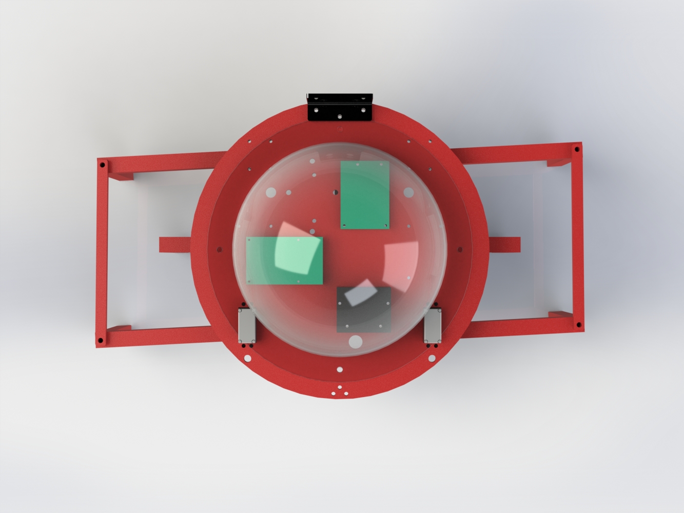
On top of the chassis is the dome, which encloses many of the components on top. It is decorated with vinyl cut black spots to look like a ladybug. The dome has a hole in the front for the wires of the cameras to connect the cameras, outside the dome, to the raspberry pi. There are also cutouts for the rear motors, preventing interference between the servos and the dome and increasing ventilation. The dome is clear to allow the viewer to see the wiring and circuitry within.