Electrical System
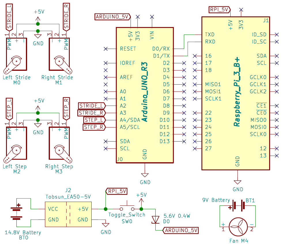
Our electrical system is fairly simple. The robot is powered by a 1550 mAh 14.8V LiPo battery. As that voltage exceeds the operating voltage of any of our components, we use a simple step down power regulator to get an output voltage of 5V. Our Raspberry Pi is connected directly to the power regulator while our Arduino and servos are connected via a rocker switch and simple circuit equipped with a Zener diode. That small circuit, seen in the schematic above, allows us to regulate the current passed to all our components while preventing power backflow from the Arduino via the Raspberry Pi. Without it, the current could pass from the battery through our Raspberry Pi, into the Arduino via its USB serial port, and then into our servos. While not harmful to the servos themselves, the low voltage would have caused them to twitch and in turn, would have resulted in unnecessary power drainage and made diagnosing mechanical problems more difficult.
All of the servos are PWM enabled and are connected to the Arduino’s digital GPIO pins via 3-pin connectors. The dual cameras used for vision are connected to the Raspberry Pi via 2 standard USB 2.0 ports.
Due to the computational power required for our robot’s computer vision, the Raspberry Pi could become extremely hot. That overheating would have caused thermal throttling and potential CPU damage, both of which would have had negative effects on the computational performance of our robot. To combat this problem, we are using a 12V fan and small aluminum heatsinks to cool our Raspberry Pi to more ideal temperatures. Although the ideal voltage for the fan is twelve, we found that a standard 9V battery is perfectly fine.