Sprint 1
Entering our first 2-week sprint, we aimed to have a robot that had simplistic yet functional legs, as well as basic control software that would allow it to walk in a straight line. Before we began designing legs, we did research on various existing leg and walking designs. We examined various quadrapods such as Boston Dynamics’ “Spot”, which have at least two servos or motors per leg, and other, simpler designs that used four-bar linkages to bend and lift the legs. We also looked at quadrapods and hexapods that moved in a variety of ways, especially ones that were able to walk upstairs. We considered these designs because we are interested in having our robot have the ability to walk on rough terrain. Originally, we thought that it would be relatively simple to make a robot that could walk on four legs, but after talking to professors and NINJAs, we found that a six-legged design might be better, as it would allow our robot to be able to balance using only mechanical systems.
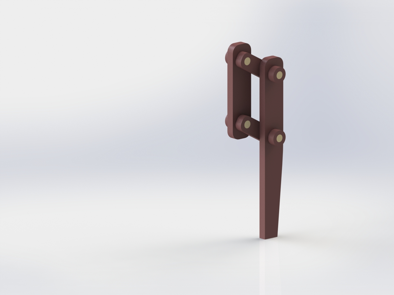
We then explored two different leg types: L-shaped bars and a four-bar linkage for each leg. We eventually decided on the L-shaped bars, as it allowed us to be able to more easily control the robot, since we would be able to actuate the front and back legs with a single servo using only a connecting bar instead of a gear train. Additionally, this design made integration somewhat simpler both because the design was simpler and also because the servo location to distance traveled conversion is very simple.
Because we initially set out to achieve a significant amount of progress in this sprint, we decided to simply prototype our robot rather than put a significant amount of time and effort into its fabrication. For a chassis, we found a relatively small cardboard box onto which we attached our legs and sensors. We decided to laser cut the legs from 1/4” MDF fiberboard so we could relatively quickly get our robot prototype assembled. However, we quickly realized that the laser-cut legs and their mounts could not support the full weight of the electronics, so we ended up re-CADing an attachment and 3D printing the entire assembly.
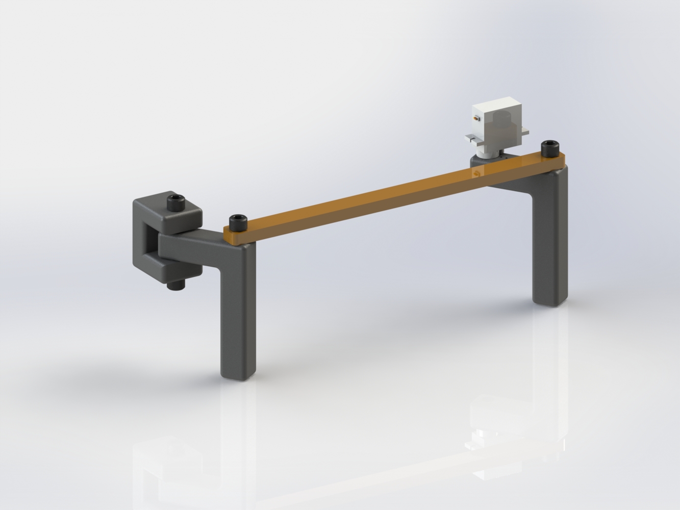
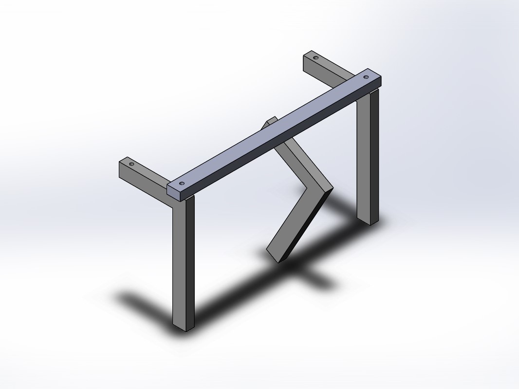
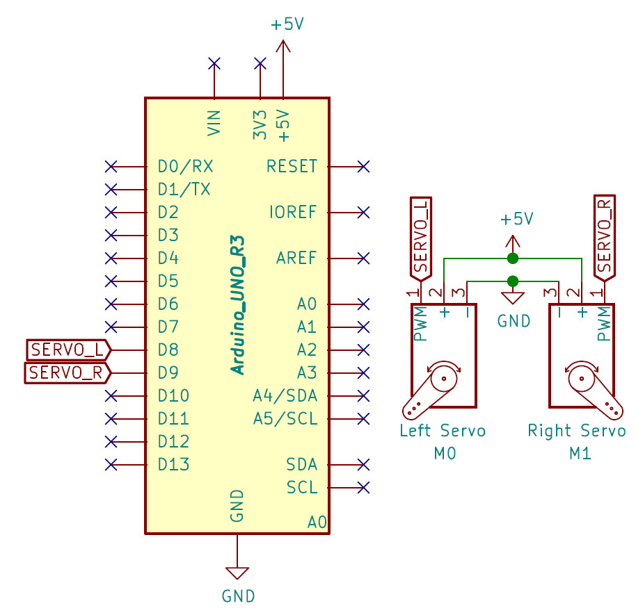
To get the legs to move we connected four servos to an Arduino Uno. The two servos attached towards the front of the robot were attached to the L-shaped legs connected by a bar. These two sets of legs would move in opposite directions, similar to how a four-legged animal walks.
At the center of the robot there was another set of servos, one on each side. Each servo had an L-shaped leg that helps lift the robot, so it can reset the lateral legs on each side. However, there was a flaw in our leg design, so the center legs collided with the bar that connected the other legs. Therefore, our robot was unable to walk. As a result, we were not able to fully reach our sprint goal, though we did learn a significant amount about our mechanical design and improvements that we needed to make.
During this sprint we learned about all the components that we need to focus on for Sprint 2. Our goals for Sprint 2 are as follows:
- Create a data pipeline between laptop and robot computer to accelerate path planning algorithm development.
- Redesign and fabricate new body of robot.
- Work on traction for legs to propel forward.
- Iterate on design of the legs so that there is a better range of motion, no unintended collision between parts, faster linear motion, and improved weight bearing.
- Do a more complete integration between sensing and mechanical movement.