Software
Link to GitHub Repository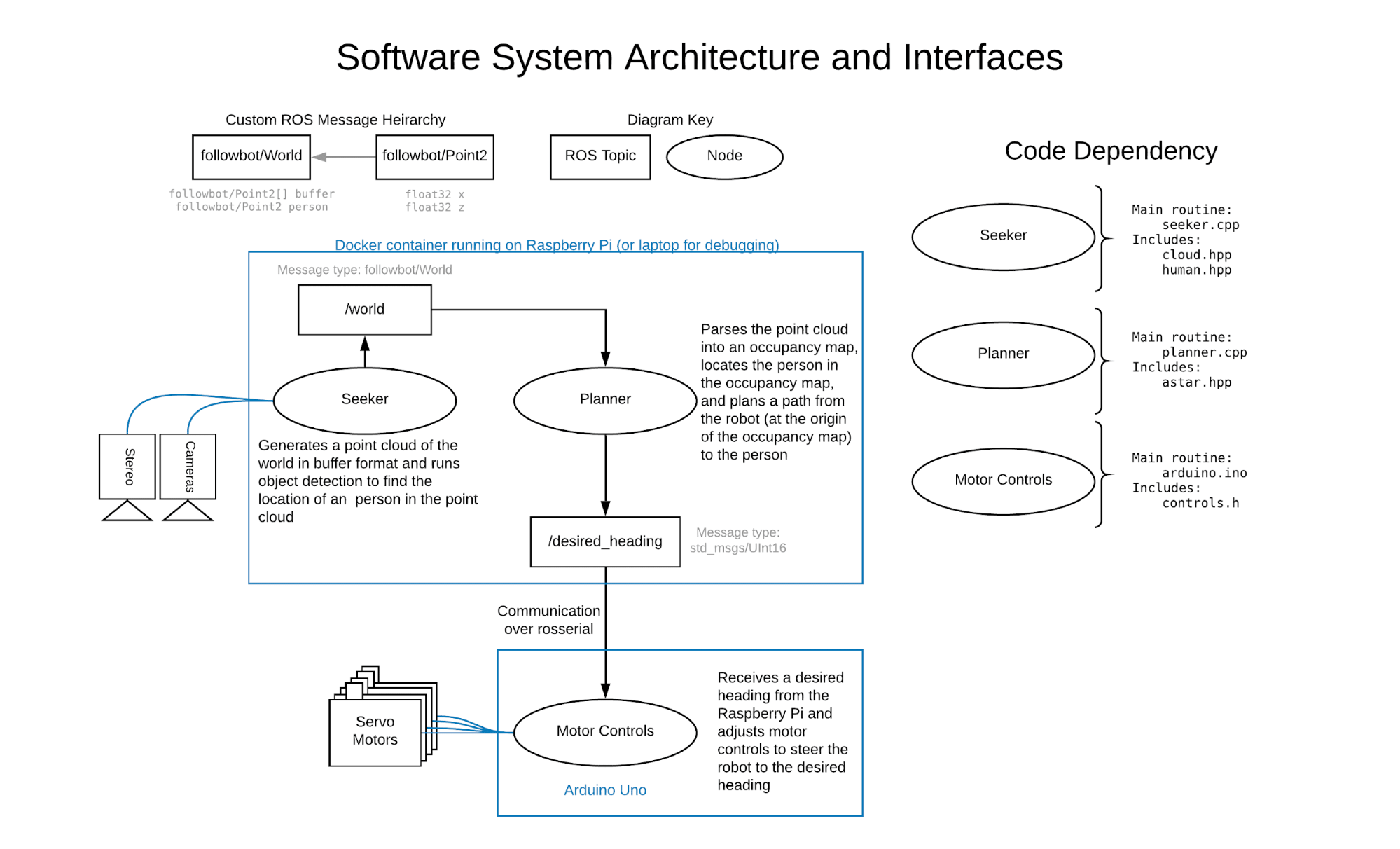
At a high level, our robot gains an understanding of the world around it by combining images from two adjacent cameras into a three dimensional point cloud. This works in conjunction with neural network-powered object detection. Using that data, it calculates a heading and walks toward a person. Our code is optimized for an Arduino Uno and Raspberry Pi 3B+ and is fast enough to perform the entire tracking and navigation cycle 3 times per second.
Environments and Optimizations
In order to create a reproducible and predictable software stack, we opted to use Docker containers. Containers isolate the codebase from our development and production machines, ensuring our software runs on both our on-board computer, a Raspberry Pi 3B+, and laptops without any hiccups.
We created two nearly identical Docker images, one to use for development and one to use for production. Both are based on a pre-built image of ROS (Robotic Operating System) Melodic on Ubuntu 18.04 Bionic and vary in only in a few ways: the inclusion of IDEs on the development image and the build optimizations used for compiling OpenCV on the Raspberry Pi. As the objective of our robot was to identify and follow individuals in real-time, we had to ensure that our code would run as quickly as possible; however, the computatinaly-limited Raspberry Pi made achieving that speed a challenging task. In order to meet our goal, we customized a build of OpenCV for the 32-bit ARMv7 processor used by the RPI 3B+. After extensive research, experimentation, testing, and configuring of the pre-trained neural network, we managed to optimize our production Docker container and increase our program’s run frequency to ~3 Hz (300ms / cycle), 16x faster than the unoptimized stock build.
Sensing and Path Planning
Throughout our codebase we took an object-oriented approach to organizing our featuresets. We incorporate the message-sending capabilities of ROS so that we can run multiple nodes asynchronously and send data between them. Not only does this help modularize our software, but it enables our code to run faster. We defined two nodes: “seeker”, which reads the cameras and parses their data into a point cloud containing a location of a person in the world; and “planner”, which filters the point cloud into an occupancy grid and calculates the desired heading of the robot using A*. Using ROS’s serial communication library, we then send this desired heading to an Arduino which adjusts the robot’s motor controls accordingly.
The data flow between the seeker and planner nodes is unidirectional, as the planner node only requires information from the seeker node to calculate a heading. Thus, the start of the data flow begins in the `collectPointCloud` method of the Cloud class, which is called from the main routine of the seeker node and is where images from each of the stereo cameras are acquired. By rectifying these two images such that there is no vertical distance between corresponding pixels, a disparity map is created where values are equal to the horizontal distance between points in the two images. We use OpenCV’s StereoBM algorithm to achieve this. While it is not the most robust of the possible disparity algorithms, it is computationally the cheapest and is appropriate for the level of detail we need. The disparity map is converted into a 3-dimensional point cloud and then converted from a matrix data structure to a buffer of 2-dimensional points. In this process, we project the points onto a plane parallel to the ground by removing their height components. Furthermore, only a subset of the 3D point cloud is used for this conversion, given by the set of points that fall within a hard-coded vertical range from the X-Z plane, distance from the robot, and vertical range, in the image plane. This reduces the computational overhead and unnecessary information for subsequent processing steps.
After this is complete, the getHumanPosition method of the Human class is called to identify the location of a person in the point cloud. We chose the YOLOv3 object detection system for its ease of use and high-level integration into OpenCV’s deep neural networks module. The person’s location in the image is identified in the following manner: after passing an image through the neural network, a series of bounding boxes with corresponding classification id’s and confidence values is returned; overlapping bounding boxes of the same class are combined into single bounding boxes using the non-maximum suppression algorithm. We deviate from the default implementation of object detection by filtering all returned bounding boxes for boxes that are classified with a “person” id. After combining the bounding boxes, we filter once again for the bounding box identified with the highest confidence; thus, we are left with a single bounding box with a high confidence that encompasses a person.
In a future iteration more advanced computer vision would enable the software to maintain a tracking lock on a particular individual between frames, using approaches such as optical flow and SLAM. A final step of post-processing is the shrinking of the bounding box (defined by a hard-coded proportion) such that the probability of pixels encompassed by the bounding box being associated exclusively with a person is increased.
All of the aforementioned object detection is contained within the detect method of the Human class called by the getHumanPosition method; this method returns a boolean that, if true, enables the getHumanPosition to find the location of the person in the point cloud. A key aspect of the object detection is that it is run using an image (arbitrarily chosen from the left camera) processed by the same rectification as the images being passed into the point cloud creation unctions. This is the rectifiedImage parameter that is passed into getHumanPosition. When combined with the image-shaped matrix of 3D points (the pointcloud parameter of this method), this means that the pixels within a bounding box from the object detector are directly related to their location in the 3D world. Using this, we take the centroid of points in the 3D world (similarly projected onto the XZ plane) defined by the bounding box to be the location of the person. This coordinate, along with the buffer of 2D point cloud points, is published in a custom ROS message to the “/world” topic. To summarize in more simple terms, using the capability of ROS to generate data structures from .msg files and publish them to its server, we make available the point cloud and human location data - accessible by an address called “world” - to any other node in the ROS cluster.
The node that accesses this data is the planner node, whose main routine serves to calculate a viable path to the person and publish a heading to the Arduino. The planner node accepts the current position of a person in the real world along with the collected point cloud, creates an occupancy map, and computes a path to the person that avoids detected obstacles. The path is computed using a rudimentary implementation of A* that calculates step cost from linear distance and path cost from Manhattan Distance. Our robot does not follow a global path so only the first step of the calculated path is used to find a heading.
Our Arduino is connected to our existing ROS cluster via a USB-A to USB-B serial cable and the Arduino library “rosserial_arduino”. Based on that broadcast heading, our robot calculates the appropriate stride length for its left and right legs. It does this by converting the input heading to a direction (forwards / backwards) and an angle range of 0-180 degrees. The remapped value is then normalized to a coefficient between 0 and 1 and used to scale the stride range of the right left. The left leg is set to its complement. This ensures that the robot will turn left when the right stride range is larger than the left and vice versa.
Software Dependencies:
- Docker
- ROS Melodic (including the catkin build system)
- OpenCV
- Including VTK for visualizations
- DNN and Stereo modules