Sprint Goals
For this sprint we wanted to finalize the CAD in order to really focus on manufacturing. We wanted to program motor, LEDs and sensors to a minimum in order to start getting the behaviors. We wanted to integrate the structure with the software and electrical, although not necessarily a minimum viable product.
Current State
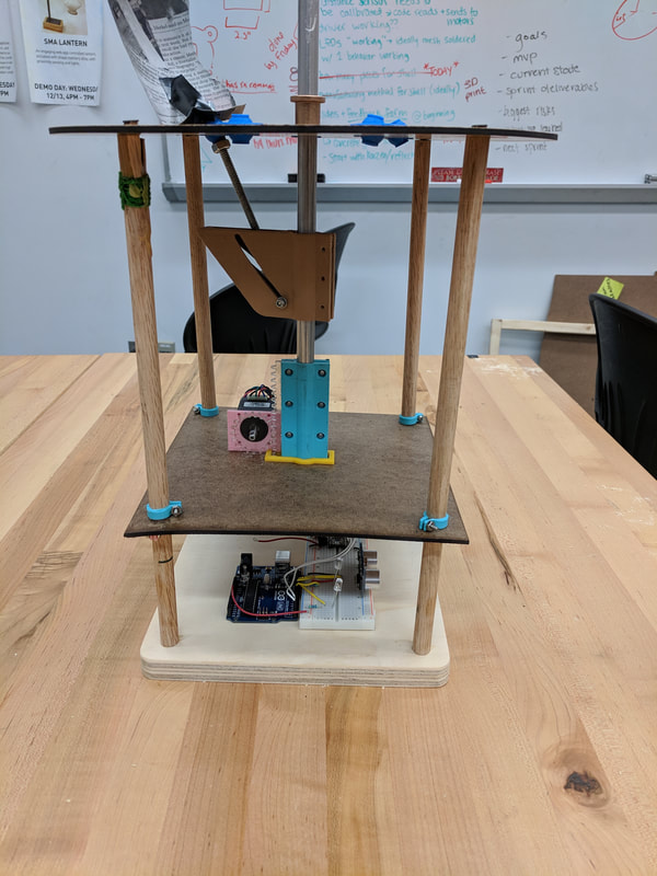
We built a prototype which is almost functional. The code, electronic, and mechanical system are all integrated. We built a mechanism to open and close a 'petal' and made the circuit respond to changes in a distance sensor through an Ardunio. However, the motor was too weak to move the assembly. This is partly due to the friction between the cam and the follower, and partly due to the fact that the motor is fairly weak. We have written code to change the behavior of the lights, but not successfully integrated it into this system
LEDs
|
We developed the LED response separate to the overall mechanical integration. We tried two separate libraries to individually address these LEDs.
The first library we tried was called NeoPixel. We found that this didn't give us the control we wanted and moved on. We next tried a library called FastLED. This libarary gave us the power to create interesting effects with our LEDs, but had poor documentation that made using it a hassle. Despite this, we stuck with FastLED for our final. We programmed two core patterns, including a scared flashing pattern as well as a pattern that traces motion. |
|
Motor and Distance Sensor
|
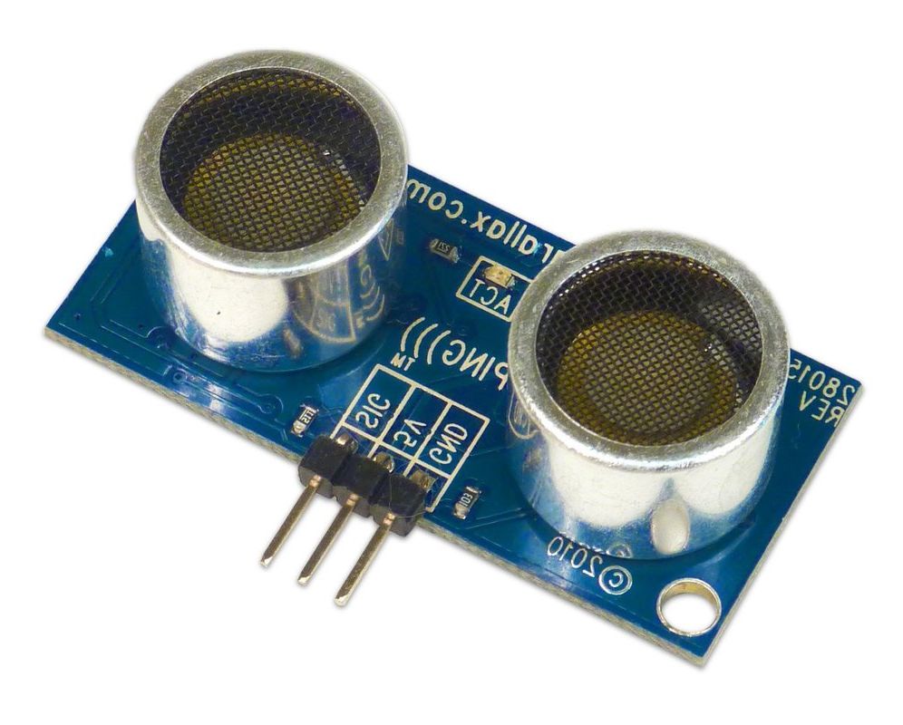
At this point the system was programmed to react to changes felt by a distance sensor hooked up to an Arduino. We programmed two motions with this input:
|
|
Mechanical
|
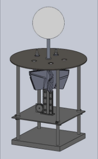
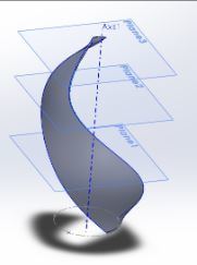
We thought about how to make the motion we wanted, and developed a plan and CAD for how to build the system. We chose to make a CAM that could twist the pedals and angle them out to create interesting motion. We also chose to drive this linear motion with a rack and pinion gear, feeling that this would give us a lot of control over the position of the petals. We also designed a frame structure to contain this system, a twist on the clock-cage plate design common to mechanical systems.
We also iterated on making 3D printed ball joints which would allow for motion rotationally and at an angle. We first considered buying these but when we saw that they would cost $17 each decided to try 3D printing them. We found that the Stratasys printers could to a reasonably good job making these bearings and after an iteration successfully printed these. Looking forward, we need to consider how to reduce the effect of friction in the system. We felt that this was due in part to the PLA we used to print the cam, and from here decided we would try to print it using ABS, learning about the potential for ABS smoothing with Acetone. |
|
Teardrop Shell
|
|
|
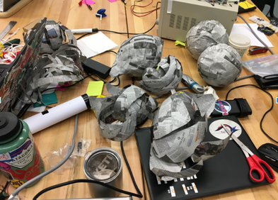
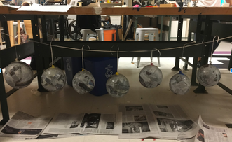
In order to start thinking about the shell, we explored different methods of manufacturing. We rapid-prototyped the effect of different numbers of petals and the shape of the petals using paper mache on balloons. We concluded from this that having an 8-piece shell was most appealing, and to get the shape we sought we would would CAD it using Blender which would allow us to 3-D print it on the Stratasys.
Next Sprint
For the next two weeks we wanted to create a functioning MVP. This meant that the LEDs would have the 'wisp' behavior and that we would have two of the modes of our sculpture done - scared and resting. We would have to change the design of our cam to reduce friction and create a sturdier frame. This MVP would also require the mechanical, software, and electrical components to be integrated. We also want to have some ideation with the teardrop shape and the exterior of the base.