The Structure
|
The Sphere & LEDs
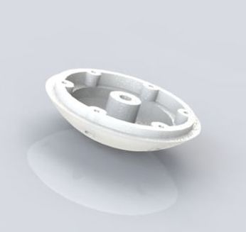
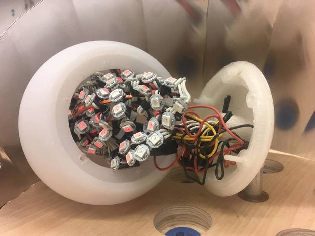
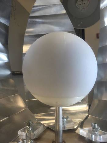
The upper section of the sphere was purchased on Amazon, and needed a base to mount it onto the main shaft. Do this by 3D printing a bottom section of the same radius, adding holes for screws and a 1/2" flanged hole for the shaft. This mount doesn't need to take a load, so make sure the flange ID allows it to press fit onto the tube. The flange has a hole in it to give the wiring inside of the sphere a way to access the hole of the tube. The lights are connected in a circle with zip ties and and then placed inside of the sphere. The assembly required to put this piece together is simply screwing the base into the holes that were already in the sphere. Fabrication: 3D Printed Parts: 3D Filament |
|
|
|
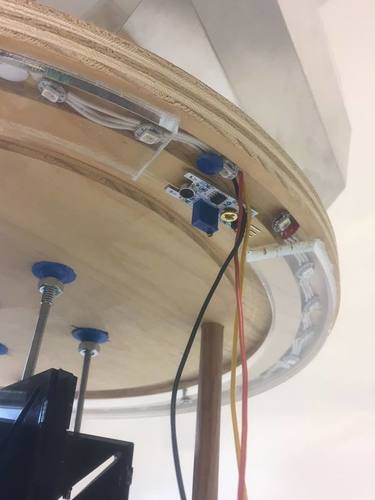
The Lower Plate & Electronics
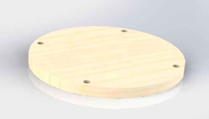
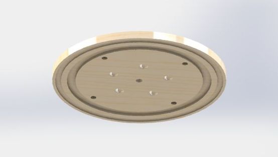
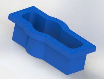
In order for the base structure to serve all necessary purposes it needs a top, middle, and lower plate. The base plate is a circular profile shape with four circular pockets for wooden dowels to press into. This lower plate also serves to mount all the electronics, which is possible by mounting them onto a scrap piece of wood and then screwing this down onto the plate. The electronics also need to be off to the side so they avoid begin hit by the rack gear.
Fabrication: Shopbot
Parts Needed: Plywood
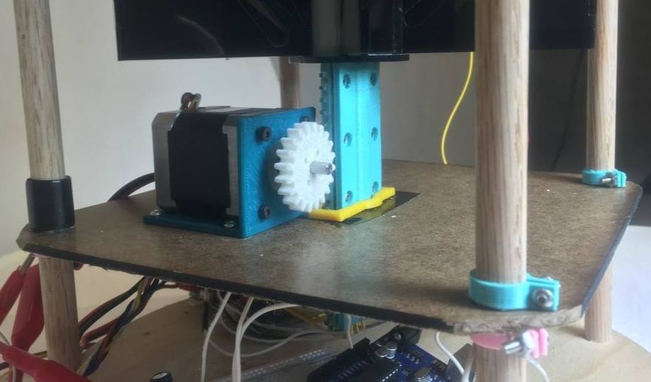
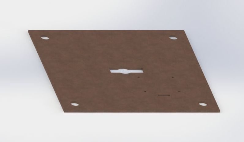
The Middle Plate
The middle plate serves to mount the motor. It is positioned in the middle of the range of motion of the rack and pinion, allowing it to move to its full extent. The plate is held in place by collars on the side shafts and the motor is bolted in using the motor mount - both of which are 3D printed.
Fabrication: Laser cut
Parts Needed: Hardboard
|
|
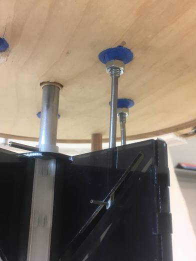
The Upper Plate
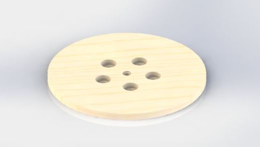
The upper plate is the most complex, containing many slots for the components. There are pockets and through holes for the ball joints and the main shaft bushing, allowing them to sit in the plate and guide motion as they are designed. There is a slot to guide the placement of the skirt and another for the LEDs. Finally, there are four holes that correspond to the pockets on the bottom plate, allowing the wood dowels to press in and complete the frame.
Fabrication: Shopbot
Parts Needed: Plywood
|
|
|
|
The Skirt
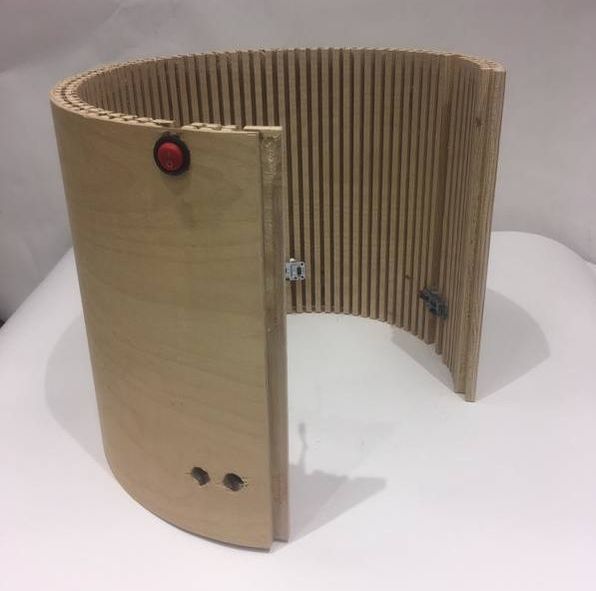
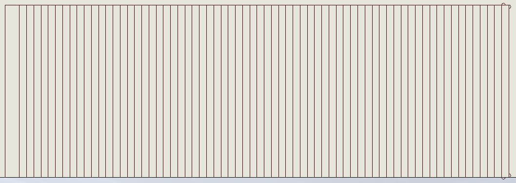
In order to contain and hide all of the mechanical and electrical components, we made a skirt to wrap around the base and which could be installed and uninstalled easily. The strategy used to create this effect with plywood is called kerf cutting, and the cutting file for this sheet can be seen below. Holes are then drilled in the sides to allow room for electrical components including distance sensors, on/off switch, and wires for the LEDs.
Fabrication: Shopbot
Parts Needed: Plywood
|
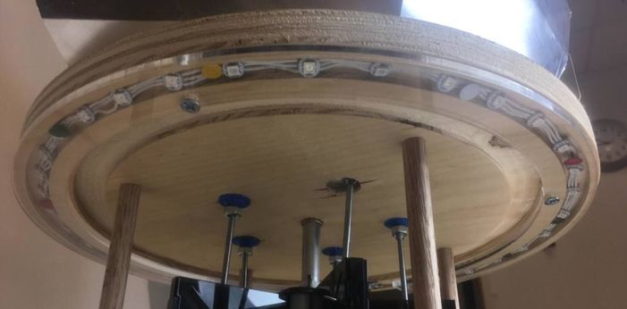
The Ring
For the upper plate there is a slot of the LEDs around the base. This is then covered by a ring with a slot for the wires to come through. This is screwed into the top plate as well. The LEDs inside of the ring are pinned into the wood, but can easily be kept in place by the ring alone if necessary. Fabrication: Laser Cut Parts Needed: Acyrlic 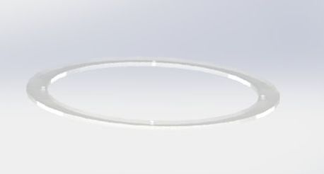
|
|
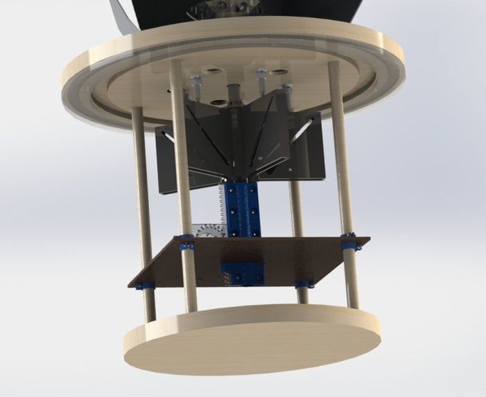
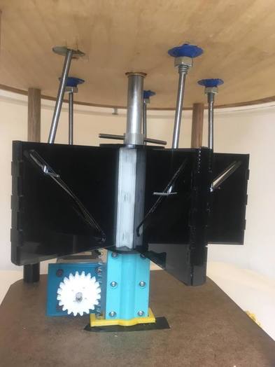
The Mechanisms
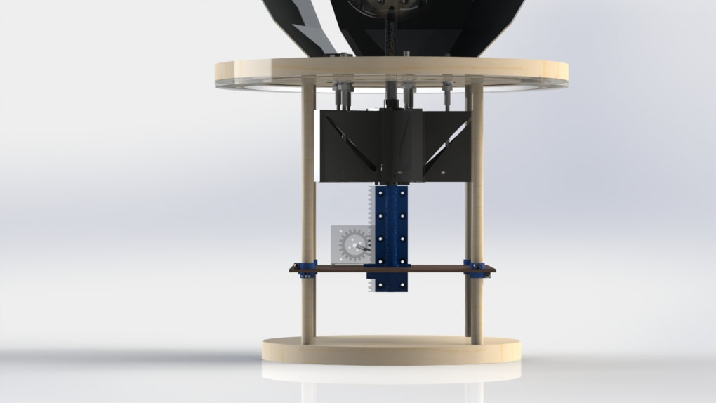
The Rack and Pinion
|
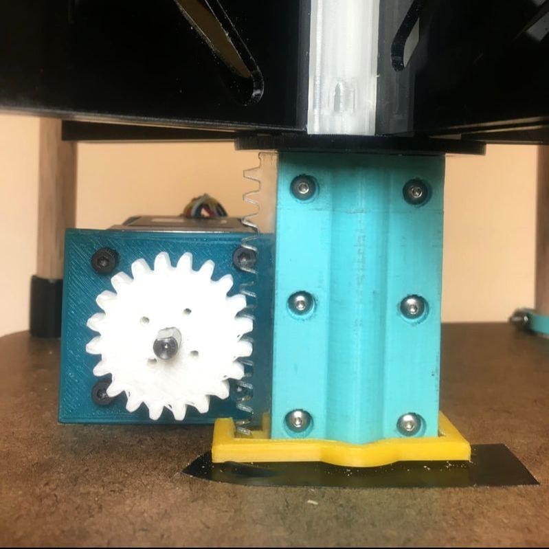
The Rack and Pinion
The designs for the rack and pinion gears are found on McMaster Carr's website. These CAD files are used to create a laser cut rack and a 3D printed pinion. To make sure the pinion gear doesn't slip there is a spring pin acting as a set screw on a partially cross drilled D-shaft of the motor. Fabrication: 3D Printed and Laser Cut Parts Needed: Acrylic and 3D Filament |
|
The Collar and Bushing
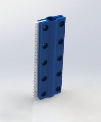
There is a long 3D printed collar with a slot for the rack to mount it to the main shaft. There are pockets in the collar for the nuts and bolt heads, and the collar is held in by using bolts only long enough to hold on but not protrude, resulting in a smooth sliding surface. There is also a 3D printed bushing for middle plate which constrained the motion of this unusual shape vertically.
Fabrication: 3D Printed
Parts Needed: 3D Filament
|
|
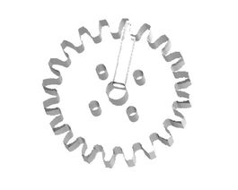
The Cam and Followers
The Cam
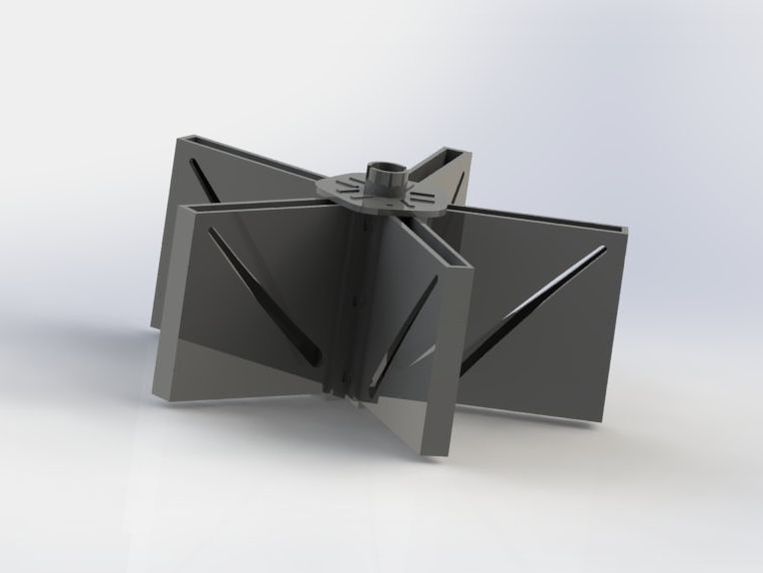
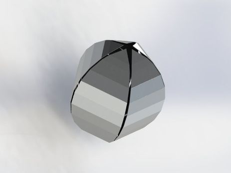
Our cam was designed in a way which would allow the petals to spread out and twist through the travel of the rack and pinion. To limit the follower and make the most reliable motion we could, the cam uses two different profiles with a space between for the follower to travel through. The two profiles work together to make the follower twist and angle through its motion. These profiles are laser cut into pieces of acrylic, which are joined at the center by a 3D printed hub. These profiles are also held in place with an edge piece maintaining the space between and a cap a the top and bottom. Acryclic-welding all these pieces together results in a cam whose sturdiness is results from the relationships between the joints. This entire thing was attached to the main shaft and locked rotationally with a spring pin.
Fabrication: 3D Printed and Laser Cut
Parts Needed: 3D Filament and Acrylic
The Followers
The followers are made from threaded rod which has a spring pin placed through it. The threads are turned off of the rod for the majority of its length at the end the spring pin is attached to, allowing it to slide in the track of the cam. This design resulted in limited friction between the acrylic and the metal pin. The end with threads was then bolted into the ball joints, locking them in place but not rotationally at the upper plate.
Fabrication: Lathe and Drill Press
Parts Needed: Threaded Rod, Nuts, Spring Pins

|
|
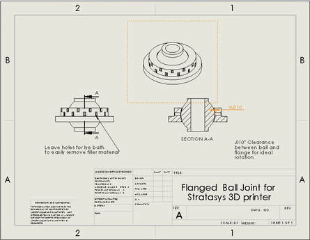
The Ball Joints
Ball bearings are needed to allow for rotational and linear movement as we wanted. In order to avoid paying the very expensive price of ball bearings and the quanitity we wanted, they are 3D printed on a Stratasys printer. The result comes from a round of experimentation in which we tested the capacity for the Stratasys to tolerance pieces printing inside of themselves. We found that .01" between the ball and socket produces a satisfying result.
Fabrication: 3D Printed
Parts Needed: 3D Filament
|
|
|
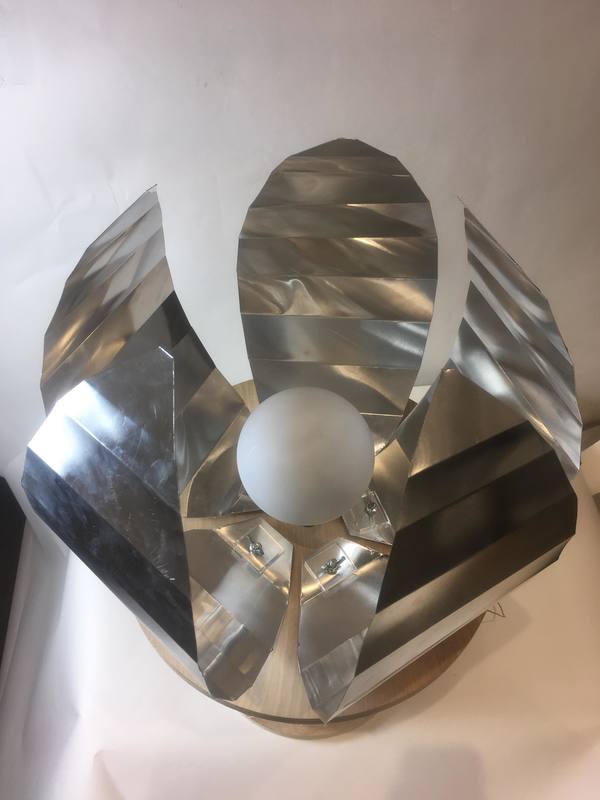
The Shell
The Pieces
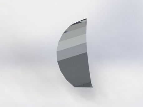
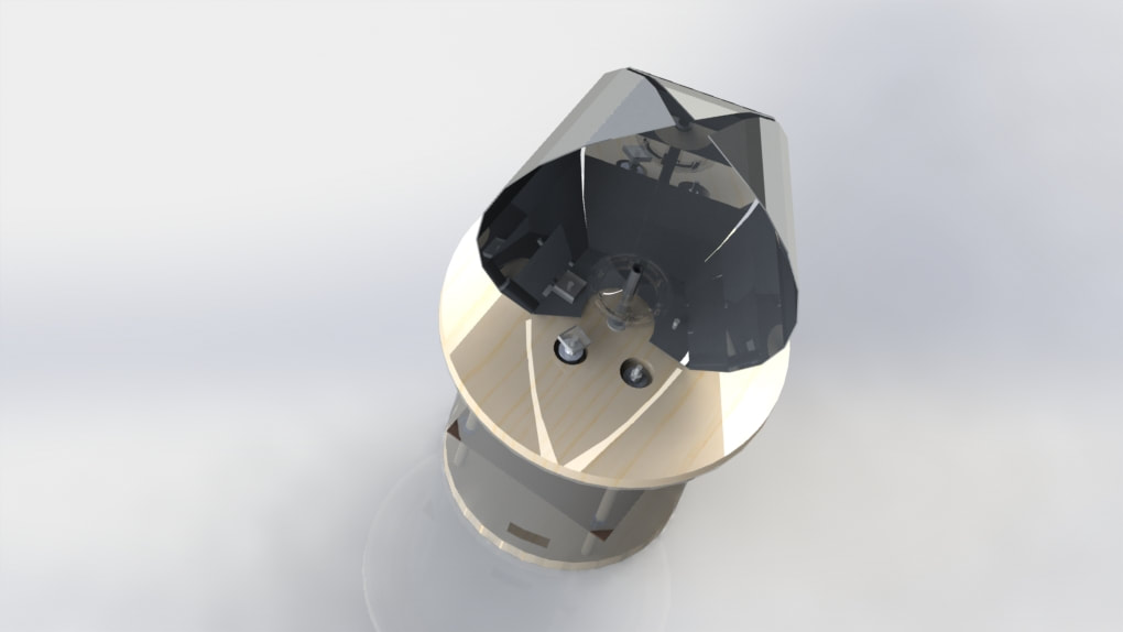
To create interesting light effects and reduces overall weight the shell is made out of sheet metal. We created petal type shapes with straight lines and multiple folds. There is a slight gap in order for light to come through regardless of shell's position. This piece is very artistic and could be made in any multitude of ways.
Fabrication: Finger press, sheet metal cutter
Parts Needed: Sheet Metal
|
|
Mounting the Shell
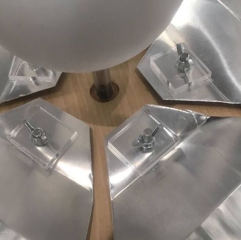
There are squares of acrylic which acts as a clamp and locks the shell rotationally. The reason for acrylic is to try and make the effect subtle, and the nuts used to lock them down match the color of the sheet metal. Between the ball joint and the shell is a spacer since the ball bearing is nested in the top plate so without this there would not be enough room for the pieces to move.
Fabrication: Laser Cut
Parts Needed: Acrylic
|
|
CAD
Solidworks Files
3D Print Files
Laser Cutter Files
ShopBot Files
Assemblies
Drawings