The Components
The Motor
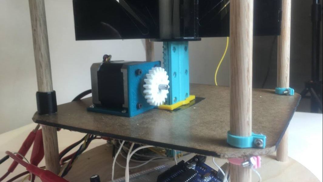
In order for the rack and pinion to slide up and down the pinion was attached to a motor. This behavior was impacted by the sensors.
In order for the rack and pinion to slide up and down the pinion was attached to a motor. This behavior was impacted by the sensors.
The LEDs
There are LEDs, inside the sphere and also around the base, all of which behave the same way. The LED's convey the sculpture's mood, and are controlled based on input from the sensor.
There are LEDs, inside the sphere and also around the base, all of which behave the same way. The LED's convey the sculpture's mood, and are controlled based on input from the sensor.
The Motion Sensors
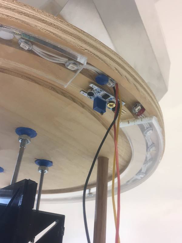
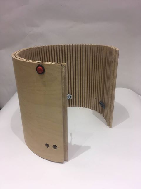
A motion sensor is embedded in the base to interact with its environment. It is mounted into the skirt and will trigger motion and light display.
A motion sensor is embedded in the base to interact with its environment. It is mounted into the skirt and will trigger motion and light display.
The Schematic
Materials:
Power:
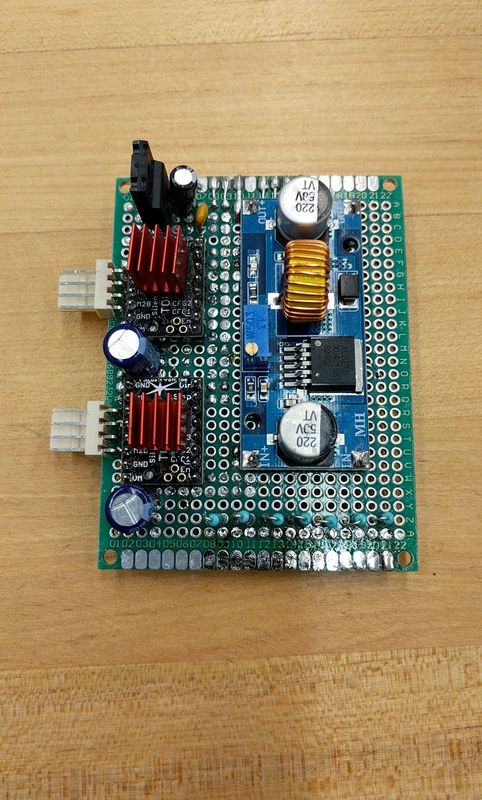
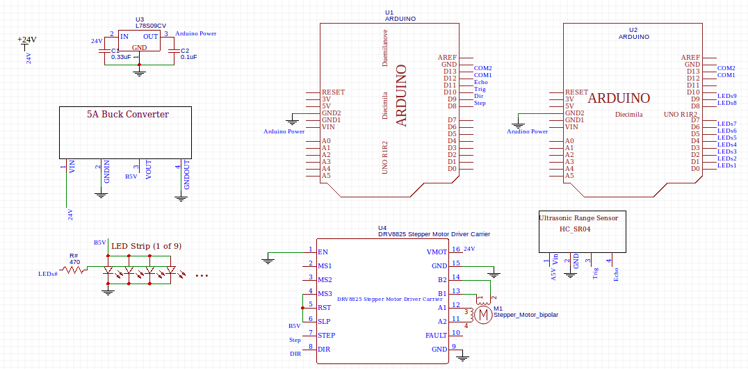
The 24 volt power supply is used to power the motor driver. This is too high for everything else in the circuit, however, so it has to be stepped down to more useful voltages. For the arduinos, we used a 9V voltage regulator. Most voltage regulators require capacitors between ground and both input and output to smooth out the signal. The 5V buck converter is used to power the LEDs due to the high current drawn from so many LEDs in parallel. If you use the module linked to above (or a similar one), the filtering and noise reduction is done for you, but if you use a simple Buck converter chip, make sure you check the datasheet for the required extra circuitry. Optionally, you can connect the 5 volt supply from the Buck converter directly to the Arduino’s 5V port (as opposed to Vin, where power normally goes), but be careful that the arduino is never plugged into a computer at the same time as the 5V supply if this is the case.
Make sure that wires carrying high current are of higher gauge. Most wires can be 20 gauge, but the main power supply and LED power should be closer to 16 or even 14.
Motors:
The ideal motor size for this machine is NEMA 17, most motors of this size will be powerful enough to open and close the Wisp. Look for a motor with inductance under about 4 milli-Henrys. Other motor drivers will work, but the DRV8825 works pretty well.
The first step in wiring up the motor and motor driver is to calibrate the current limiter in the motor driver. POLOLU offers a great guide on how to do this here under Description. The basic process involves tuning the potentiometer with a screwdriver until Vref reads half the current you want to put through the motor. More current means the motor will be more powerful, but it will also get hotter. Too little current could cause the motor to skip steps and otherwise underperform. Set the current no higher than the current limit given by your motor’s datasheet.
This is not shown in the schematic, but a 100 uF capacitor should be placed connecting VMOT and GND. This protects the driver from voltage drops and spikes.
LEDs:
In order to light the orb in the center of the sculpture, you will need around 150 addressable LED’s, soldered into nine strips (varying in length from about 4 to about 24 LEDs) such that they can be arranged in a spherical shape inside the orb. Each should connect to the five volt supply from the Buck converter. As mentioned above, if this is carried on one wire to the LED’s, make sure you use a slightly higher gauge wire. Each strip of LEDs should have one data lead, and each data lead should run through a 470 Ohm resistor to one of the Arduino’s digital pins. Make sure to connect the LED’s with stranded wire, as solid core wire is too stiff to form the sphere out of with breaking leads.
Arduinos and The Sensor:
The sculpture uses two arduinos, one for running the LEDs and one for running the motor and sensor. They need to talk to each other, so connect pins 12 and 13 together. Make sure all pins listed in the code match the actual connections. If not, change one of them. It is recommended that you power the Arduino with a 9 or 12 V regulator, such as linked to above, but if this causes problems, the Buck converter can power the arduinos, but again, be careful not to power an Arduino with a USB cable (such as while flashing code) and the Buck converter at the same time.
The sensor is very easy to work with. It has four pins, two for power and ground and two for producing and reading a signal. Plug them in to the correct pins and the sensor should work perfectly.
- Two Arduino Unos
- One NEMA 17 Stepper Motor
- One DRV8825 stepper motor driver
- One HC-SR04 Ultrasonic distance sensor
- Nine strips of Neopixel LEDs or similar
- One Buck Converter module capable of supplying 5 amps (For example, this one)
- One L78S09CV Linear Voltage regulator
- Nine 470 Ohm resistors
- Capacitors: One 100 uF, one 0.1 uF, and one 0.33 uF
- One 24V Volt 4 Amp Power supply
Power:
The 24 volt power supply is used to power the motor driver. This is too high for everything else in the circuit, however, so it has to be stepped down to more useful voltages. For the arduinos, we used a 9V voltage regulator. Most voltage regulators require capacitors between ground and both input and output to smooth out the signal. The 5V buck converter is used to power the LEDs due to the high current drawn from so many LEDs in parallel. If you use the module linked to above (or a similar one), the filtering and noise reduction is done for you, but if you use a simple Buck converter chip, make sure you check the datasheet for the required extra circuitry. Optionally, you can connect the 5 volt supply from the Buck converter directly to the Arduino’s 5V port (as opposed to Vin, where power normally goes), but be careful that the arduino is never plugged into a computer at the same time as the 5V supply if this is the case.
Make sure that wires carrying high current are of higher gauge. Most wires can be 20 gauge, but the main power supply and LED power should be closer to 16 or even 14.
Motors:
The ideal motor size for this machine is NEMA 17, most motors of this size will be powerful enough to open and close the Wisp. Look for a motor with inductance under about 4 milli-Henrys. Other motor drivers will work, but the DRV8825 works pretty well.
The first step in wiring up the motor and motor driver is to calibrate the current limiter in the motor driver. POLOLU offers a great guide on how to do this here under Description. The basic process involves tuning the potentiometer with a screwdriver until Vref reads half the current you want to put through the motor. More current means the motor will be more powerful, but it will also get hotter. Too little current could cause the motor to skip steps and otherwise underperform. Set the current no higher than the current limit given by your motor’s datasheet.
This is not shown in the schematic, but a 100 uF capacitor should be placed connecting VMOT and GND. This protects the driver from voltage drops and spikes.
LEDs:
In order to light the orb in the center of the sculpture, you will need around 150 addressable LED’s, soldered into nine strips (varying in length from about 4 to about 24 LEDs) such that they can be arranged in a spherical shape inside the orb. Each should connect to the five volt supply from the Buck converter. As mentioned above, if this is carried on one wire to the LED’s, make sure you use a slightly higher gauge wire. Each strip of LEDs should have one data lead, and each data lead should run through a 470 Ohm resistor to one of the Arduino’s digital pins. Make sure to connect the LED’s with stranded wire, as solid core wire is too stiff to form the sphere out of with breaking leads.
Arduinos and The Sensor:
The sculpture uses two arduinos, one for running the LEDs and one for running the motor and sensor. They need to talk to each other, so connect pins 12 and 13 together. Make sure all pins listed in the code match the actual connections. If not, change one of them. It is recommended that you power the Arduino with a 9 or 12 V regulator, such as linked to above, but if this causes problems, the Buck converter can power the arduinos, but again, be careful not to power an Arduino with a USB cable (such as while flashing code) and the Buck converter at the same time.
The sensor is very easy to work with. It has four pins, two for power and ground and two for producing and reading a signal. Plug them in to the correct pins and the sensor should work perfectly.
