Materials
(Schematic and additional information about the electrical components can be found in the electrical section)
- 2 Arduino Unos
- 1 Ultrasonic distance sensor
- 1 Stepper Motor
- 156 addressable RGB LEDs
- Arduino IDE (at the time of writing, version 1.8.5 for Windows Desktop was used. Using version 1.8.6 and 1.8.7 with the FastLED library caused the compiler to crash repeatedly.)
- FastLED Arduino library
- SpeedyStepper Arduino library
System Overview
The software component of the Wisp serves 4 main purposes:
- Collect User Input: Continuously collect user-input data from the outward-facing ultrasonic distance sensor.
- Determine State: Process the data and determine which of the 4 possible states the Wisp should take.
- Control the Lights: Based on the state, send commands to the addressable RGB LEDs within the central sphere and around the skirt.
- Control the Motors: Check the current position of the stepper motor controlling the opening and closing of the petals, determine if a motion would be possible, and then proceed accordingly.
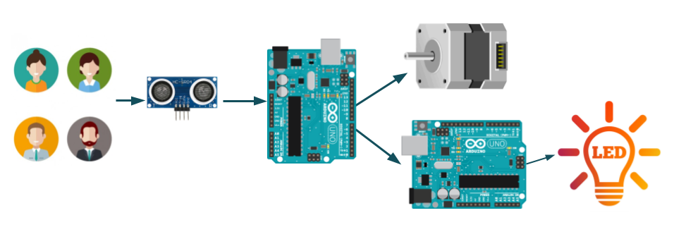
The ultrasonic distance sensor data is continuously processed by the first Arduino. The Arduino reads and processes data at the beginning of each loop and decides which of the four states--stoic, scared, timid, or trusting--the Wisp should be in (see the Behaviors section below for more information). Upon determining the Wisp’s current state, the first Arduino does three things. First, it sends a 2-bit binary signal corresponding to the current state to the second Arduino. Second, it checks to ensure that moving the motor would not cause the petals to open or close beyond their intended design. Third, the motor movement is processed, assuming it is safe to do so. Otherwise, the motor remains in its current position.
The second Arduino’s main purpose is to control the 156 RGB LEDs within the Wisp (121 within the central sphere and 35 around the base of the skirt). In order to keep the LEDs in sync with the rest of the system, the second Arduino continuously reads the binary signal sent from the first Arduino, and sets its state to match the first Arduino. It then updates the LEDs accordingly.
The second Arduino’s main purpose is to control the 156 RGB LEDs within the Wisp (121 within the central sphere and 35 around the base of the skirt). In order to keep the LEDs in sync with the rest of the system, the second Arduino continuously reads the binary signal sent from the first Arduino, and sets its state to match the first Arduino. It then updates the LEDs accordingly.
Table of Behaviors
There are four possible states for the Wisp to take on. The logic which determines how each state is defined is central to the character of the Wisp, so it is very important that it is both robust and identifiable to to the audience. We define the four states as seen in the chart below.
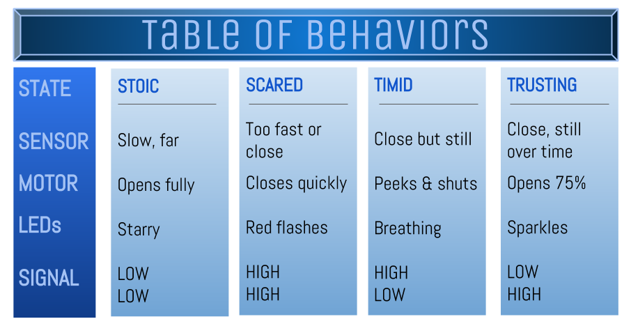
Each of the four light blue boxes defines a behavior--stoic, scared, timid, or trusting. The distance sensor readings that correspond to the initialization of each of these four states is the first entry of each box. The motor and LED responses to these states are listed next, and the signal corresponds to to the appropriate 2-bit binary signal sent from the first Arduino to the second (more on this in the “2 Arduinos” section below). More information about the information provided in the chart is provided below.
Stoic
Stoic
- Sensor Input: The audience must keep out of the range of the distance sensor or stay at a medium range without moving.
- Motor Response: The petals open to their full span.
- LED Response: Blue LEDs fade on and off like stars.
- Corresponding Signal: LOW, LOW (or 0, 0) is sent from the first Arduino to the second
- Sensor Input: The audience either moves too quickly while in the range of the sensor, or they walk too close.
- Motor Response: The petals shut quickly.
- LED Response: Red LEDs flash and blink.
- Corresponding Signal: HIGH, HIGH (or 1, 1) is sent from the first Arduino to the second
- Sensor Input: the audience must be close to the sensor and remain very still.
- Motor Response: The petals open slightly, pause, then close.
- LED Response: Lights breathe between blue, pink, purple, and red.
- Corresponding Signal: HIGH, LOW (or 1, 0) is sent from the first Arduino to the second
- Sensor Input: the audience must be close to the sensor, remain very still, and stay there for a period of time.
- Motor Response: The petals open 75% of their full capacity
- LED Response: Bright, multi-colored lights blink energetically
- Corresponding Signal: LOW, HIGH (or 0, 1) is sent from the first Arduino to the second
Challenges and Considerations
With 156 addressable RGB leds, a stepper motor, a distance sensor, and code split up between two Arduino Unos, and four possible states for the Wisp to take on, the code for this project presents a few challenges. We discuss the major considerations that were factored into the design of the code, as well as the reasoning behind each choice.
Delays
Typically we expect users to interact with Wisp in somewhat slow, easy to track motions. However, fast changes in movement are bound to happen, and delay statements could easily cause the Arduinos to miss them. To counter this, almost all situations where delay statements are commonly found are replaced with timers.
The code for Arduino 2 (the LED controller), has no delay statements. This presents an interesting challenge, because if LEDs refresh as fast as the Arduino runs through a loop, they appear dimmed and twitchy. To prevent this without making the Arduino unresponsive to input, we incorporated timers and conditional if statements. This allows us to regulate the refresh rate of the LEDs to 80 and 150 ms, depending on the state of the Wisp.
Delay statements are present in 2 places in the code for the first Arduino. The first is used to collect ultrasonic distance sensor data, and is only a few microseconds (effectively instantaneous so there is nothing to worry about). The second place is a 5-second delay in the scared state. This was incorporated to emphasize the scared behavior of the Wisp. The delay prevents the Wisp from switching to any other state while scared, and is okay because there is no user input that can immediately “un-scare” the Wisp.
2 Arduinos
2 Arduino Unos are used in the Wisp. This design decision was made to issues we encountered when running code for the entire system on one Uno during our third sprint. 2 Arduinos actually gives the added benefit of controlling the motors and the LEDs independent from each other (which is important since both the LEDs and the stepper require some consideration of timing in one way or another). The only consideration is that communication must be established between the two.
To get two Arduinos to communicate with each other, we make use of Arduino’s built-in digitalWrite() and digitalRead() functions. By wiring 2 sets of digital pins to each other (2 on the first Arduino, 2 on the second), we effectively create a one-way, 2-bit channel for sending commands from one Arduino to the other. This allows us to overcome the difficulty of ensuring that the LEDs stay in sync with the rest of the system.
Stepper Motor
There are a couple of important considerations regarding the stepper motor. The stepper motor powers the linear actuator, which moves up and down to open and close the petals of the Wisp. This is a limited range of motion, so the position of the stepper motor needs to be tracked at all times. Mistakes in tracking can cause the stepper motor to attempt to drive the linear actuator either through the upper or lower plate, which is, of course, not good for our electrical and mechanical system. To account for this, the maximum number of steps is defined as a global variable, and before any commands to the motors are sent, the first Arduino checks to see whether the proposed motion could be executed within the pre-defined, safe range of motion. The particular stepper motor we used for the Wisp had 8x microstepping, meaning that one full revolution was 1600 steps. For this reason you will see in the code that all step intervals are multiplied by 16.
Ultrasonic Distance Sensor and Choosing a State
The ultrasonic distance sensor is the most straightforward of all of the components in the system. It takes precedence in the code, since the Wisp prioritizes data from the user above all else. Therefore, data is read from it at the beginning of every loop. It is processed by calculating both the distance and the difference between the current and previous distance (a scaled up version of the velocity). States are then determined based on the values of distance and velocity (except for the trusting state, which also incorporates a measure of time, as seen in the Behaviors chart above). The values are either determined to be above or below a set cutoff value chosen based on experimentation.
Code Breakdown
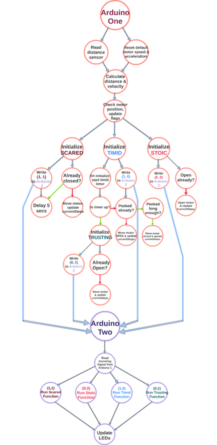
There are 2 scripts required to run the Wisp: one for the Arduino reading the distance sensor, determining the state, and controlling the motor, and one for the Arduino controlling the LEDs. The figure below breaks down the architecture of the two scripts. Green arrows represent flow if the condition is true, red represent the flow if the condition is false. The full source code is also available at the bottom of this page.
Motor Demo
A demonstration of the motor reacting to the input from the distance sensor.
LED Demo
The LEDs have four different modes as written before based on the sensors, working with the motor. The lights around the base and in the sphere work together.