MECHANICAL SYSTEM OVERVIEW
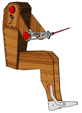
The main goals for our mechanical system were to:
1. Provide appendages to play different drums in a drumset
2. House the electrical system
3. Create the “Rocker-Dude” aesthetic that our team is looking for
Our final mechanical system is made up of four main parts: two moving appendages, a head, and a static body. The moving appendages consist of a leg and an arm --both actuated by 12V DC motors. The arm and leg have very different mechanical systems but are driven by similar motor commands. The motor is spun forwards for the downstroke and then reversed for the recoil. The hand downstroke incorporates a wrist flick actuated by a passive bicycle brake line system.
SUBSYSTEM 1: ARM
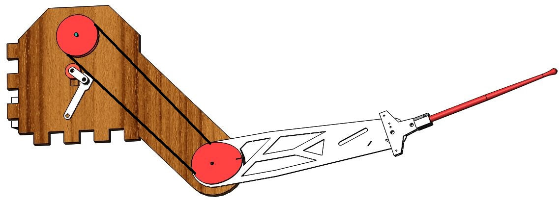
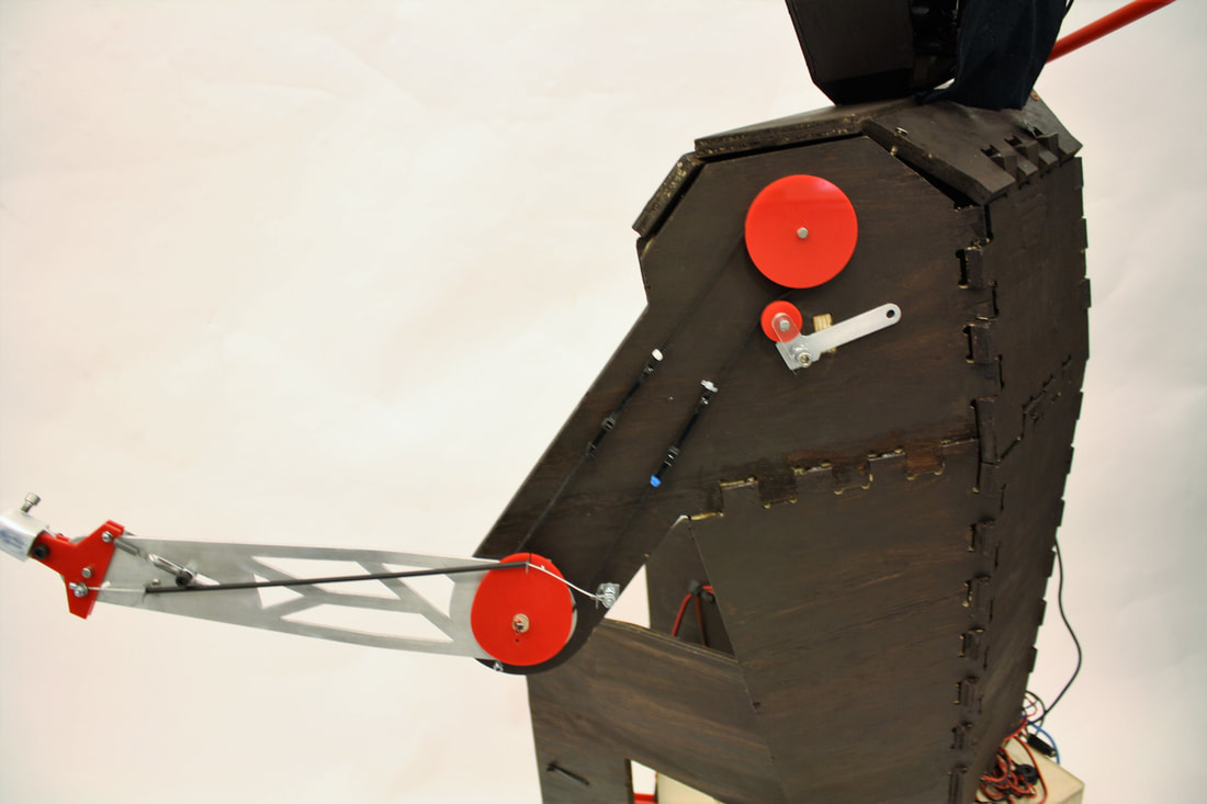
The arm is driven by a 12V DC motor from AndyMark. Because the motor needed to be housed within the body and we wanted the arm to actuate from a point more like an elbow, we used a direct drive belt to rotate the actual arm.
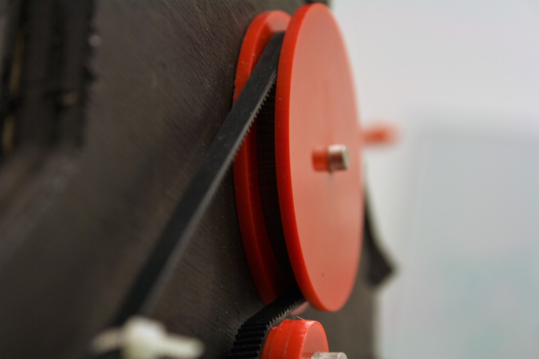
We used a belt usually used in Perusa 3D Printers, and we laser cut pulleys for it to run on. Custom making the pulleys gave us a lot of freedom to play with gear ratios and get things sized perfectly. We could also make them to fit onto custom shafts and lock into the arm with pins for further rigidity.
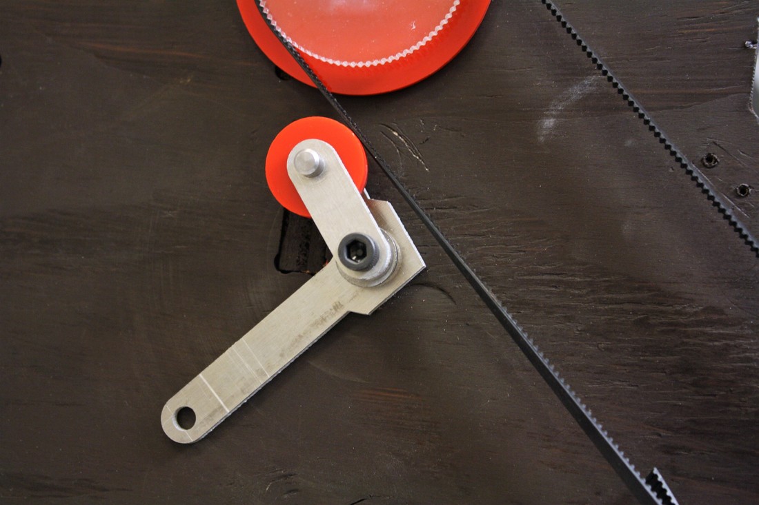
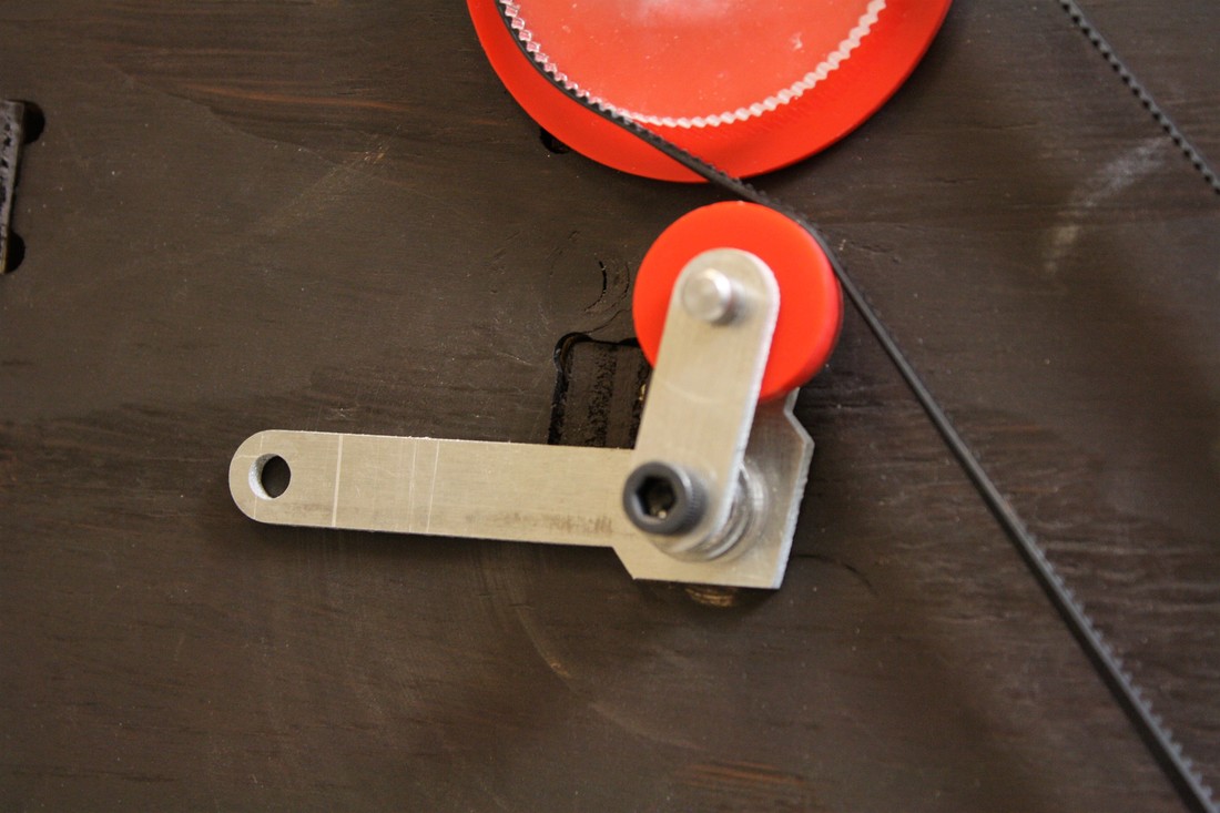
To ensure that the belt stayed tight on the pulleys, we implemented a belt tensioning system that essentially pushes up on the belt with a pulley that rotates when the belt moves over it. This pulley increases the belts travel distance, picking up any slack in the system.
To ensure that the belt stayed tight on the pulleys, we implemented a belt tensioning system that essentially pushes up on the belt with a pulley that rotates when the belt moves over it. This pulley increases the belts travel distance, picking up any slack in the system.

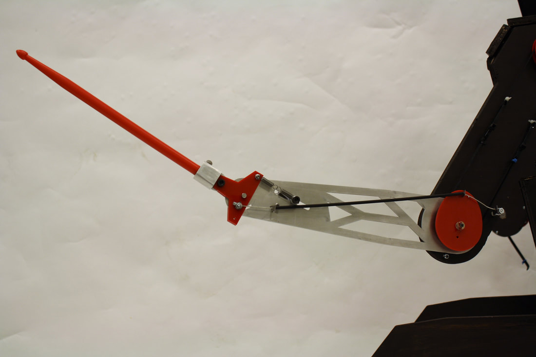
The pulley at the far end of the belt is directly attached to the arm, which we water jet from 1/8" aluminum sheet. This part was fabricated with metal rather than wood or acrylic like the rest of the robot because the stresses on it are higher and the metal in the center of the arm adds to the hardcore aesthetic. When the motor at the top spins forward, this arm is driven down, hitting the drum with the drumstick attached to the end.
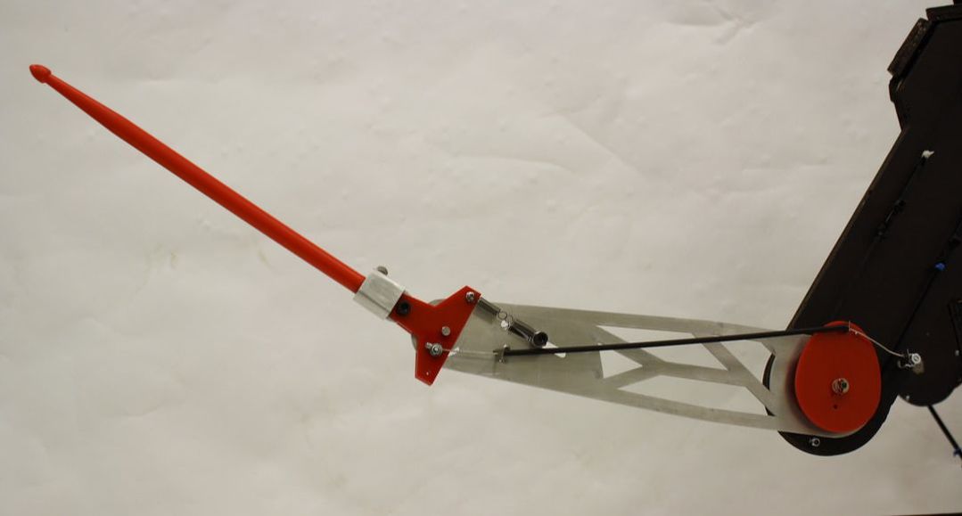
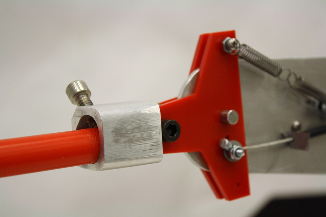
To get the humanoid wrist-flick at the end of our arm motion, we implemented a passive system with a bike brake line. When the arm pulls down, the brake cable is pulled back, causing the wrist to pivot down. When the arm comes back up, the brake cable is pushed back, pulling the wrist back to straight.
To get the humanoid wrist-flick at the end of our arm motion, we implemented a passive system with a bike brake line. When the arm pulls down, the brake cable is pulled back, causing the wrist to pivot down. When the arm comes back up, the brake cable is pushed back, pulling the wrist back to straight.
This set-up allowed us to get motion at two joints, like a human, while using only 1 motor. This simplified the system electrically, and allowed us to keep the arm of the robot sleek.
SUBSYSTEM 2: LEG
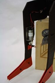
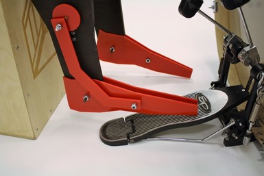
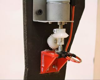
The leg is driven by the same 12V DC motor from AndyMark as the arm. The motor is mounted facing down on the calf of the leg so that it stays low profile. This required us to use a set of bevel gears to transfer the rotation to the foot though. The end of the perpendicular bevel gear drives a small cam that a tendon is attached to.
This tendon pulls the foot up when it is at the top of the cam and pushes it back down at the bottom of the rotation. The foot is also rotating about a pivot point at the ankle, which gives it the look of a foot tapping. In order to get enough force on the pedal to depress it enough to actually play the bass, we weighted Boyo’s calves with lead shot. This keeps Boyo weighted down and leaning forward at the correct angle to play the bass drum.
This tendon pulls the foot up when it is at the top of the cam and pushes it back down at the bottom of the rotation. The foot is also rotating about a pivot point at the ankle, which gives it the look of a foot tapping. In order to get enough force on the pedal to depress it enough to actually play the bass, we weighted Boyo’s calves with lead shot. This keeps Boyo weighted down and leaning forward at the correct angle to play the bass drum.
SUBSYSTEM 3: BODY
The body serves the function of holding the arms, legs, and head in the position needed to perform the drumming while taking the form of a humanoid aesthetic. The wooden structure also provides a rigid structure to mount bearings and motors. We chose to use plywood as the main material since it worked with our budget, and could make a pleasing, finished look when stained.
A functional body could have been as simple as a rectangular prism with holes in the side for motor and bearing mounting, but wouldn’t have aligned with our aesthetic goals. To best fit the humanoid shape, we used polygon shapes that fit together with finger joints that generally mimic the proportions of a human body.
A functional body could have been as simple as a rectangular prism with holes in the side for motor and bearing mounting, but wouldn’t have aligned with our aesthetic goals. To best fit the humanoid shape, we used polygon shapes that fit together with finger joints that generally mimic the proportions of a human body.
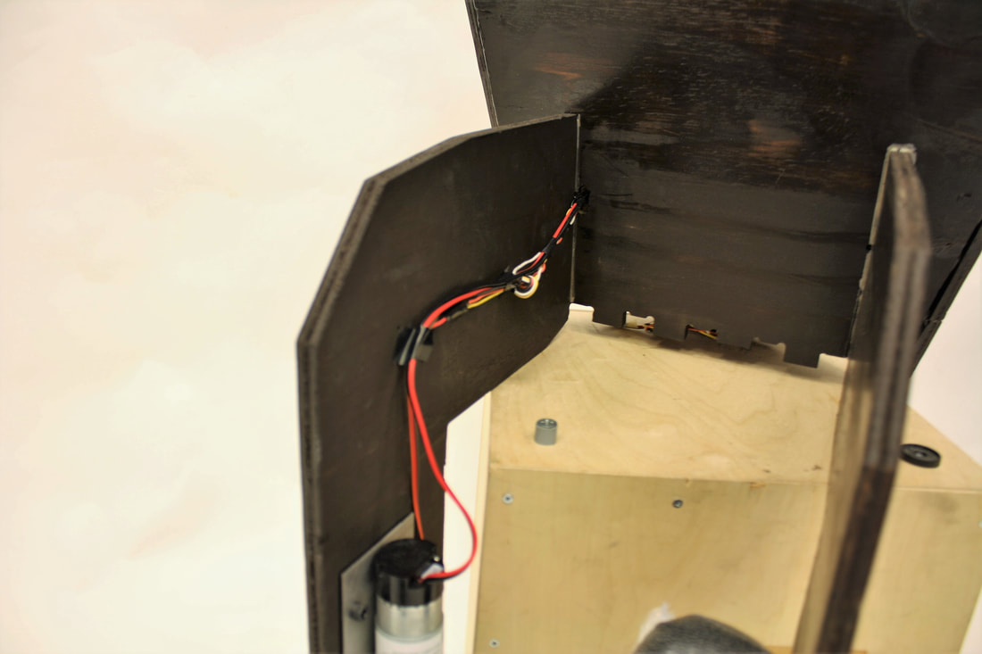
Wires are routed through the internal cavity of the body up through a hole in the top of the body that leads to the head without being visible from the outside. The only external wires interface with the motor assembly on the leg, and are routed along the side of the leg.
SUBSYSTEM 4: HEAD
The main purpose of the head is to house the electrical system and the speaker. We needed a safe place to keep the circuit as it is fairly fragile, and the microphone in the circuit needed to be directly next to the speaker. Additionally, our humanoid figure would have looked fairly strange without something on top of its shoulders, so we decided to build a head to hold everything.
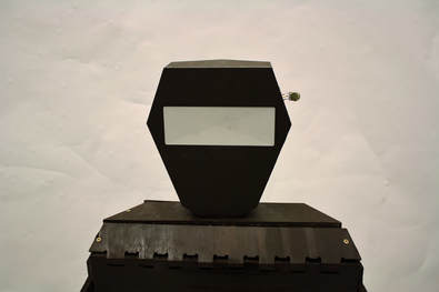
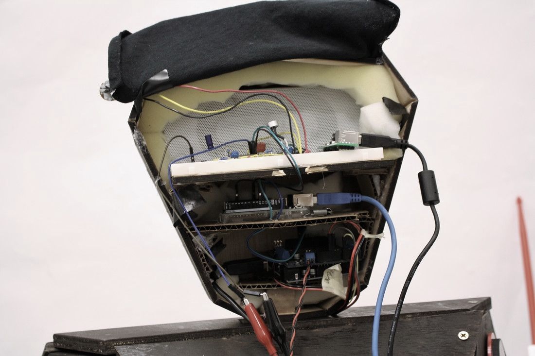
The head is vaguely ovaloid and made out of laser cut sheets of thin plywood. The angular shape keeps with the overall aesthetic of our robot. The top half of the head is taken up by a double sided Bluetooth speaker. One side plays out to the audience, and the other plays to the microphone in the circuit. Underneath the speaker, there are shelves for the breadboard and the Arduinos.
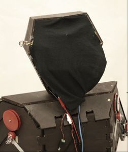
The inside of the head is packed with an insulating foam to help protect the microphone from external noises (including the drumming itself). It also acts to hold things secure inside the head. The back is closed off with a black curtain that velcros on and off for easy access to the electronics.
The inside of the head is packed with an insulating foam to help protect the microphone from external noises (including the drumming itself). It also acts to hold things secure inside the head. The back is closed off with a black curtain that velcros on and off for easy access to the electronics.
