As we worked over the course of this project, there was a significant amount of work and research done on the electrical side that didn't necessarily make it into the final product. A rapid prototyping approach was utilized to reach our goals: design, build, test, repeat.
Audio and Beat Detection Circuit Process:
The identified goal for the circuit was to determine the beat of from a live audio signal, and then generate a signal that an Arduino would easily interpret for motor commands. In order to tackle this larger goal, the task was divided into audio filtering and analog impulse to DC conversion. There were several premade chips on the market that had this functionality like the Sparkfun sound Detector (SEN-12642). These chips were purchased to test and understand their functionality as well as allow for early integration with motors. The sparkfun chip worked by amplifying audio signals, rectifying it then finding the peaks of the signal through an envelope follower, then using a schmitt trigger to convert it from analog to digital and outputting a DC wave.
This chip only included some of the functionality we desired for the final product. In order to make it more customizable, the chip was recreated on a breadboard, giving us the freedom to add new stages for increased functionality and change components to reflect the audio signals we were detecting. This satisfied our first task of audio impulse to DC conversion. However the chip detected the impulse purely by the amplitude of a wave, therefore a loud metronome beep would lead to a beat being detected however this system did not work for finding the down beats in songs because a song has instruments playing all the time - not just on the beat.
In order to tackle this challenge we experimented with adding a filtering stage to this circuit. Because the downbeat of a song was often determined by the bass or kick drum, we decided to filter the audio so only these low frequencies would pass through. Intuitively, we felt a low pass filter would remove any high frequency noise, as well as the high frequency voices and instruments being played simultaneously in the song.
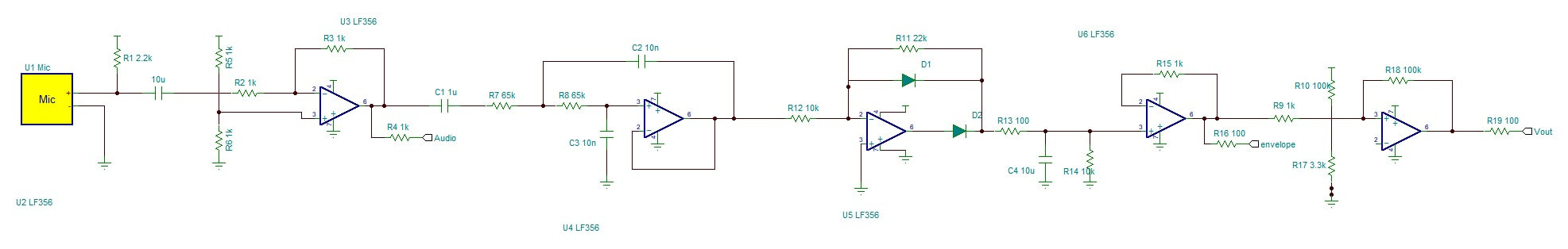
Circuit based on Sparkfun Chip
We experimented with both passive low pass filters and active Sallen-Key low pass filters with varying characteristic frequencies and then amplified the filtered signals in order to restore some of the attenuated magnitude. However the filters were not accurate enough. They reduced the amplitude of much of the song, but did get us our desired result. We incrementally stepped up the order of the passive low pass filters from first order to 6th order hoping to increase the accuracy of the filter by making a sharper cut-off. however In order to identify the problem we ran bode plots of each filter we experimented with to determine if they were behaving as expected. In retrospect this was a viable method however the cut off frequency we selected was not correct. This was supported by passing song audio through matlab simulations of the lowpass filters we were constructing on bread boards.These visualizations confirmed that we were reducing the amplitude of more of the signal than we anticipated. From these visualizations we saw no clear evidence that the specific low pass filters we were working with would filter for low frequency kick drums at the accuracy we needed.
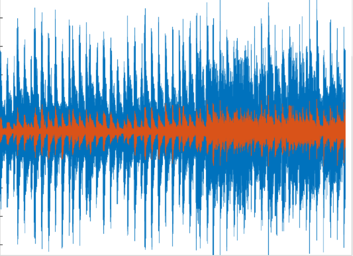
MATLAB simulation of song through filter. Blue is original signal. Orange is filtered signal.
As a result, we made a design pivot, moving away from the original low pass filter method and instead utilizing two high pass filters to replicate the behaviors of a band pass filter. We came across this method in new research into how others have implemented beat detection circuits at http://www.kirklau.com/beatx.htm. Upon construction, of the new circuit we ran into inconsistencies in our outputs. The signal sometimes railed at 0 and other times railed at 5 volts. We hypothesized this might be due to nothing defining the DC voltage level in the latter stage op-amps. By adding a large resistor to ground after the peak detector and low pass filter in the conversion stage as denoted by the circuit diagram,we attempted to prevent any leakage current through the final op-amp.
The final circuit accurately detected the beats of songs by filtering for low frequency kick drums. The resulting detection was not amplitude or sound dependent, rather it was based on the frequency of the audio. This independence made the circuit robust to changes in volume of the speaker or heavy vocals or other music tracks.
Some limitations of the final circuit included the fact that the final potentiometer used in the converting stage of the circuit had to be tuned at the start of each new song. Additionally, if the speaker was either not loud enough to be detected by the microphone or too loud that the microphone overloaded, it would not detect the beat.
|
|
|
Speaker vs Audio Input:
Deciding how the circuit would receive the audio was an important decision that dictated how the rest of the circuit and and the the drummer experience would play out. Ideation led us to two potential streams, either auxiliary cords input or microphone/speaker based audio. The aux cord input would prevent any external noise from the room or the sound the drummer makes from being detected. However, it would also require either a device or phone to be connected to the head of the drummer to play music. For user convenience, we decided to use a double sided bluetooth speaker, with one outward facing side projecting music to the people watching the drummer and one inward facing side that is picked up by a microphone. This system ensured that the drummer could connect to any phone or device within bluetooth range however it led to some additions to the electrical enclosure. Sound absorbing foam was added around the circuit to prevent the noise of the drummer drumming from interfering with the sound from the speaker.
Deciding how the circuit would receive the audio was an important decision that dictated how the rest of the circuit and and the the drummer experience would play out. Ideation led us to two potential streams, either auxiliary cords input or microphone/speaker based audio. The aux cord input would prevent any external noise from the room or the sound the drummer makes from being detected. However, it would also require either a device or phone to be connected to the head of the drummer to play music. For user convenience, we decided to use a double sided bluetooth speaker, with one outward facing side projecting music to the people watching the drummer and one inward facing side that is picked up by a microphone. This system ensured that the drummer could connect to any phone or device within bluetooth range however it led to some additions to the electrical enclosure. Sound absorbing foam was added around the circuit to prevent the noise of the drummer drumming from interfering with the sound from the speaker.