Integrated System Circuit:
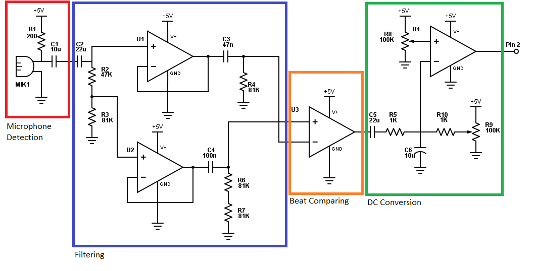
There are two actuated parts on the drummer, an arm and a foot. They are each controlled by 12V DC motor. These motors are powered via an adafruit motor shield and Arduinos. Two arduinos are used to control the system. The first calculates the beat of the music based on the input from the beat detection circuit and the other controls the mechanical behavior. On the motor attached to the foot, a 10K potentiometer was used to track position. The circuit below was used to connect the motors, arduinos and beat detection circuit.
Beat Detection:
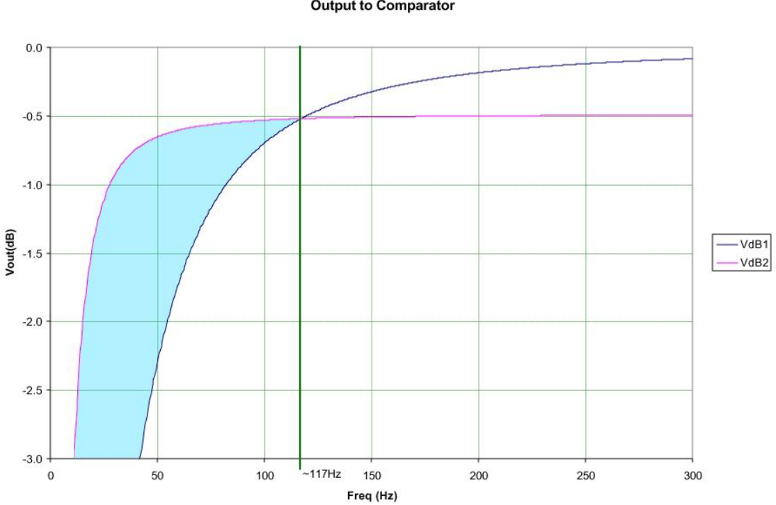
Our team wanted to improve our circuit design skills, so we decided to do beat detection in analog hardware instead of a software programming containing Fourier analysis. Our beat detection circuit is broken up into 4 stages, microphone detection, filtering, beat comparing, and DC conversion. The microphone used in our microphone detection stage is a sparkfun electret microphone. It is hooked up based on the technical documentation provided by the site. This feeds into the next stage, filtering. Here we use a voltage divider to duplicate and slightly change the magnitude of the signal and run each side through first order high-pass filters. One cut off frequency is 42 Hz and the other is 10Hz. The below bode plot illustrates the attenuated frequencies. This double high pass filter system was inspired by the method of beat detection found on http://www.kirklau.com/beatx.htm. These two signals are passed through a comparator. By subtracting the two signals from each other only frequencies below the cross frequency 117 Hz remain, as highlighted in blue in the bode plot. This filtering method prevents higher frequencies of other instruments and voices from passing through and by attenuating any low frequency noise. It utilizes the rolloff of non ideal filters to make this possible.
We send the resultant signal through a large capacitor (22uF) and a lowpass filter. This creates an envelope of each beat, resulting in a peak. Following this, a large potentiometer was added in order to reduce leakage current and to ground our reference. The final op-amp converted the analog signal of the peak detector into a DC square wave. This was done by comparing the signal to a reference voltage determined by a potentiometer. This allowed a user to fine tune the circuit to each song. If the signal was above this reference voltage, the op-amp railed the output high if not it was railed low. This converted the analog signal into a DC wave that was easily detectable by the Arduino.
Understanding Song frequencies:
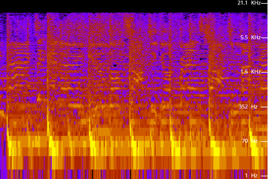
In order to determine and then verify the cut off-frequencies needed for the filters in the beat detection circuit we performed audio spectrum analysis to better understand the frequencies present in a song. Below is a spectrogram of Taylor Swift’s “Never Getting Back Together”. The kick drum, shown as periodic pulses in bright yellow are at a frequency below 70Hz. These spectrograms also helped select songs that the drummer is capable of playing in 4/4 time. Using the insight from these visualizations several pop songs with repetitive and consistent kick drum components were selected.
In order to determine and then verify the cut off-frequencies needed for the filters in the beat detection circuit we performed audio spectrum analysis to better understand the frequencies present in a song. Below is a spectrogram of Taylor Swift’s “Never Getting Back Together”. The kick drum, shown as periodic pulses in bright yellow are at a frequency below 70Hz. These spectrograms also helped select songs that the drummer is capable of playing in 4/4 time. Using the insight from these visualizations several pop songs with repetitive and consistent kick drum components were selected.


