ARM
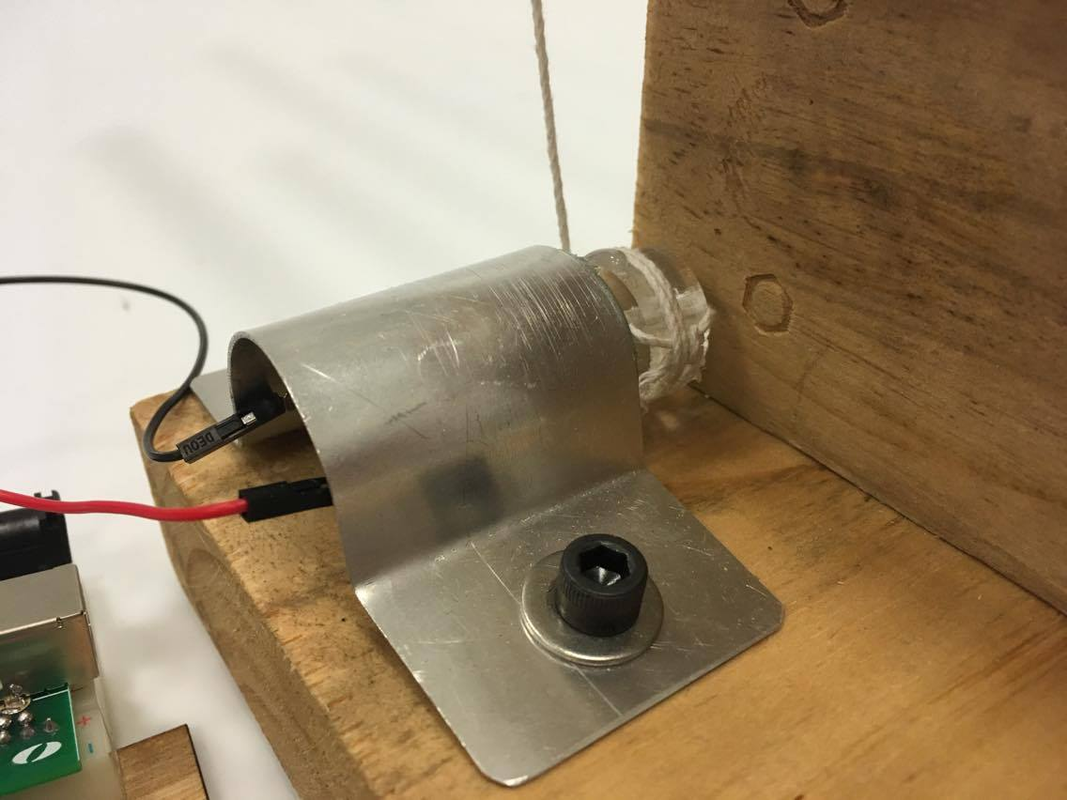
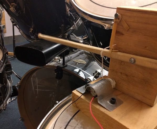
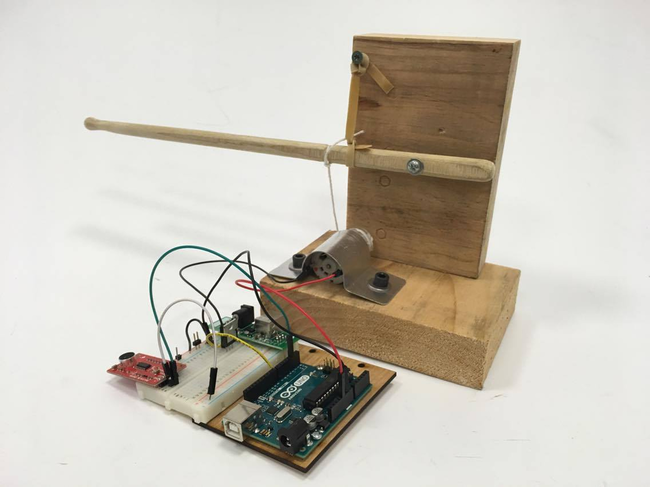
Our mechanical design for the arm started with inspiration from an Instructable on making a robot drummer, which we implemented for the first sprint. In essence, we attached a drumstick to a pivot and pulled it down using a string attach to a pulley on a small DC motor. When the motor released, the stick was pulled back up by a rubber band attached at the top. While getting this system working, we did a fair amount of calibration on where to attach the string and the rubber band to the stick to get the right travel and the right torque to pull it back up. We also had to iterate on designs for holding the string onto the pulley in a way that it could wrap without getting tangled and also not fall off.
|
|
The purpose of implementing this system was to get a proof of concept of the idea that we could create some sort of reasonable drumming sound with a mechanical system. We realized quickly though that we did not want to pursue this exact actuation method moving forward though, as it did not allow for the humanoid look we were going for, and was not very robust.
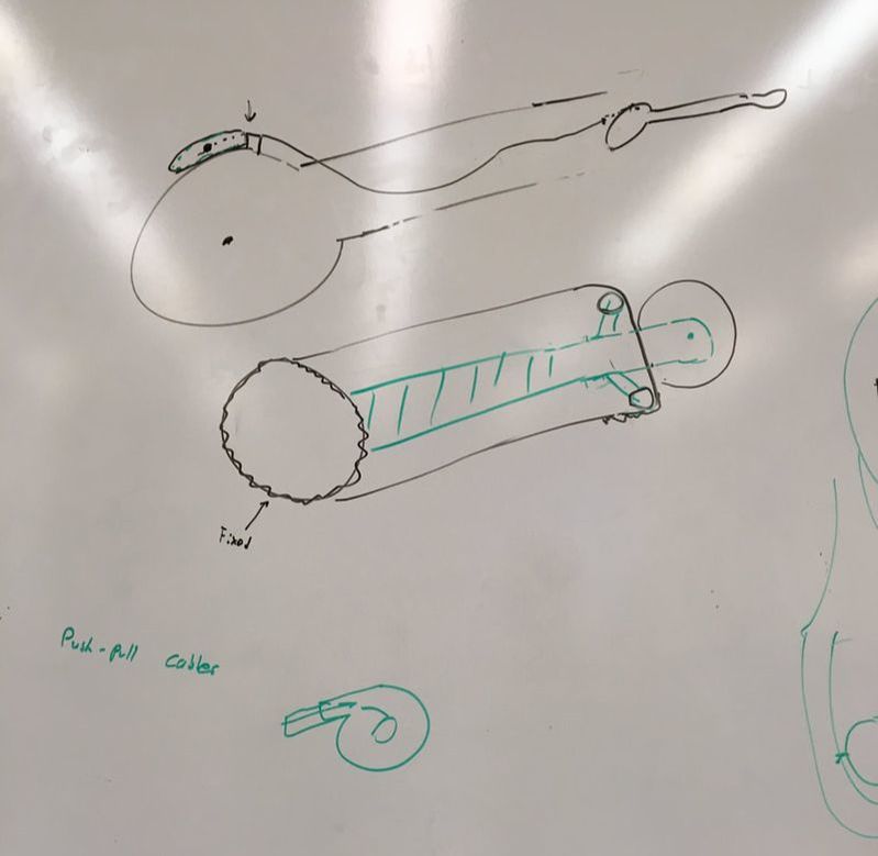
Moving into sprint 2, we decided to redesign the arm with a set of linkages rather than just one string. This would allow us to mount a motor inside the body and have the arm actuating further out. Another thing we designed for is being able to run the motors in only one direction and have the arm continuously move up and down. We knew we wanted to only use one motor for the arm, and that we wanted it to spin continuously, so we spent some time drawing different types of linkages up on the board that fit our requirements.
|
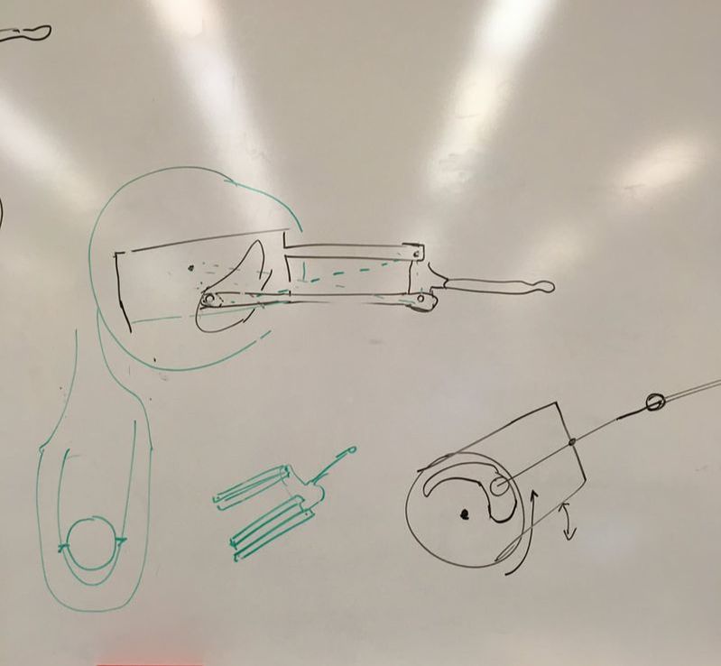
|
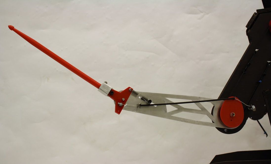
From this ideation, we decided to move forward with a one to one gear train where the driven gear was missing two thirds of the teeth. This gear was connected to a second full gear with a cam that pulled the arm up and down. This allowed the gear to spin, actuating the arm, and then release contact, allowing the arm to fall back down (aided by a rubber band).
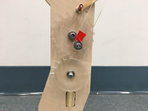
We went through a couple of iterations of gear design for this implementation, and also started working on a passive wrist flick mechanism. We decided to use a brake cable from a bike to pivot the wrist when the arm passed a certain point in its rotation, but weren’t able to fully implement it.
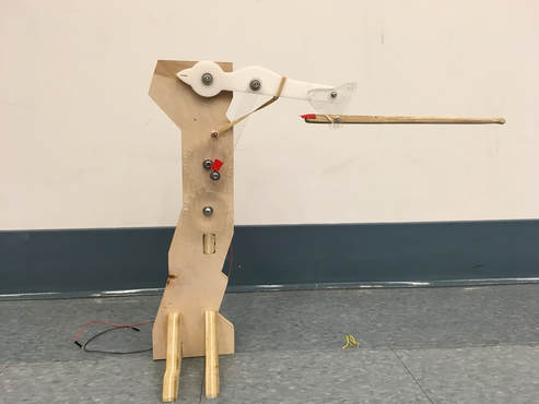
We realized while calibrating this system that because the falling motion of the arm was not controlled, there was a lot of play in how it reacted. Often the arm would fall to quickly and get caught in the first gear, causing it to drift or get stuck. Even though we originally had a goal of being able to actuate the system while running the motor in only one direction, we decided that the complications and lack in robustness that it was causing were no longer worth it. So, we pivoted to a direct drive system where the motor is connected to the elbow with a belt and pulley system.
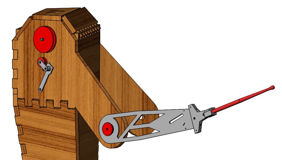
Over the course of sprints three and four, this system was refined into our final robot arm, described more in depth in the mechanical documentation. This system included a finalized version of the wrist flick as well as finalized parts made of new materials. This meant swapping out the clear acrylic we used for prototyping with red acrylic and sheet metal parts that better fit the aesthetic.
Over the course of sprints three and four, this system was refined into our final robot arm, described more in depth in the mechanical documentation. This system included a finalized version of the wrist flick as well as finalized parts made of new materials. This meant swapping out the clear acrylic we used for prototyping with red acrylic and sheet metal parts that better fit the aesthetic.
|
|
LEG
We started the design process for the foot pedal by deciding whether we wanted to build something to push the physical pedal, or something to hit the drum, bypassing the pedal. We decided that because we wanted our drummer to be able to play on any set of drums without being a part of the drums themselves. In other words it would be a replacement for a drummer instead of the drummer and drum set, so with the option of hitting the pedal. The mechanical design for our foot started with some brainstorming on how best to get enough force to push down the bass pedal. We knew that the pedal requires a fair amount of force to push down, so for proof of concept in sprint one, we built a pedal pusher that dropped a heavy weight on the end of the pedal to depress it and hit the drum.
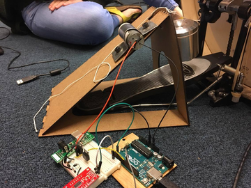
Read We ran into problems with this system fully functioning. While the mass was heavy enough to actually depress the pedal, the cheap motors that we had in the beginning had trouble lifting it up. We also had problems with the mass sliding off the pedal rather than pushing it down because there wasn’t enough friction between the two. To combat this, we essentially put a sticky foot on the bottom of the weight that we made by hot-gluing a pattern on the surface. This fixed the sliding problem, but not the motors, so we discontinued this method of actuation.
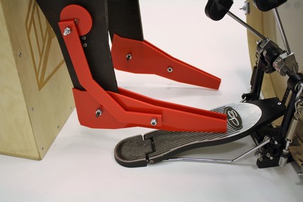
Due to the result of the first iteration and and our design decision to make the robot more humanoid, we pivoted our design for the foot drastically to a design to one that resembled a real human foot. For this design, we used the same type of AndyMark motor that we used on the arm. To keep it low profile we mounted the motor sideways on the side of the leg, and used bevel gears to transfer the rotation through the plywood leg. The shaft coming out of leg turns a cam that pulls the foot up and down. Read more about the final design in the Mechanical Documentation!
Due to the result of the first iteration and and our design decision to make the robot more humanoid, we pivoted our design for the foot drastically to a design to one that resembled a real human foot. For this design, we used the same type of AndyMark motor that we used on the arm. To keep it low profile we mounted the motor sideways on the side of the leg, and used bevel gears to transfer the rotation through the plywood leg. The shaft coming out of leg turns a cam that pulls the foot up and down. Read more about the final design in the Mechanical Documentation!
BODY
During the first two sprints, we were mainly focused on getting the arm mechanics working, so the body was mostly just a holder for the arm. The first sprint the body was entirely comprised of two 2X4s screwed together to make a base. The second sprint became slightly more refined, with a more aesthetic angular base manufactured on a CNC router. For our final body, we constructed an angular humanoid shape of intersecting polygons based the dimensions off of a real human. The sections were designed to fit together with finger joints and be fabricated with the shopbot (CNC router).
The body also incorporates structures to hold the sheet metal motor mounts in their correct positions, as well as the aluminum bearing housings for the arms.
The body also incorporates structures to hold the sheet metal motor mounts in their correct positions, as well as the aluminum bearing housings for the arms.
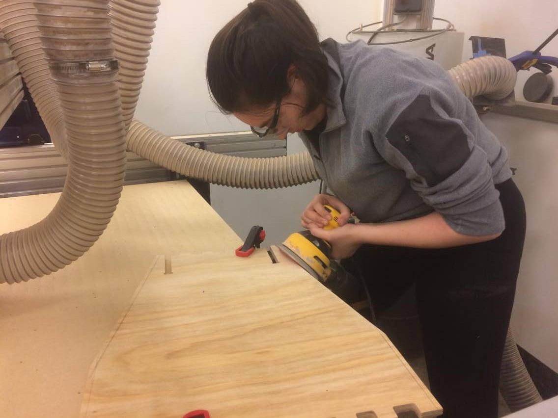
Sam sanding some edges for the body.
|
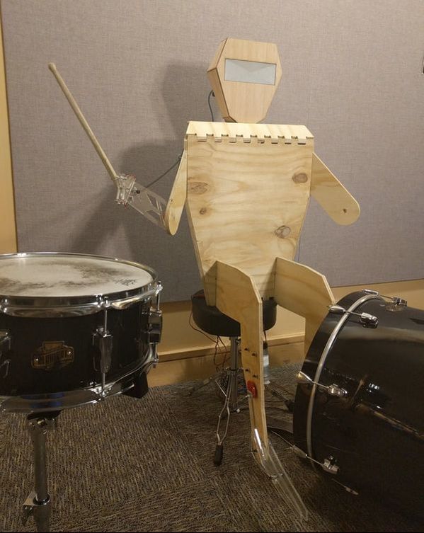
Un-stained Boyo.
"He needs a shirt or some shorts" - Anon |
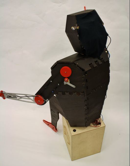
Stained Boyo.
"Wow, that's a beautiful robot." - Anon |