Housing
Final Design
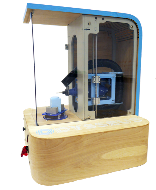
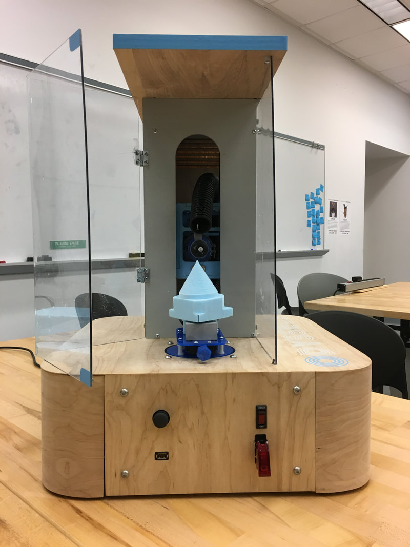
As the primary support for all other systems, the housing has to be designed to be resilient, accessible, and aesthetic. To do this, we developed a curved plywood shell covering the lower mechanical and electrical components, to which is attached the central MDF frame that supports the linear motion mechanisms and the upper hood of the housing. Integrated throughout these are mounting points for the safety shield, ventilation fan, vacuum hose, and control panel.
Industrial aesthetic
|
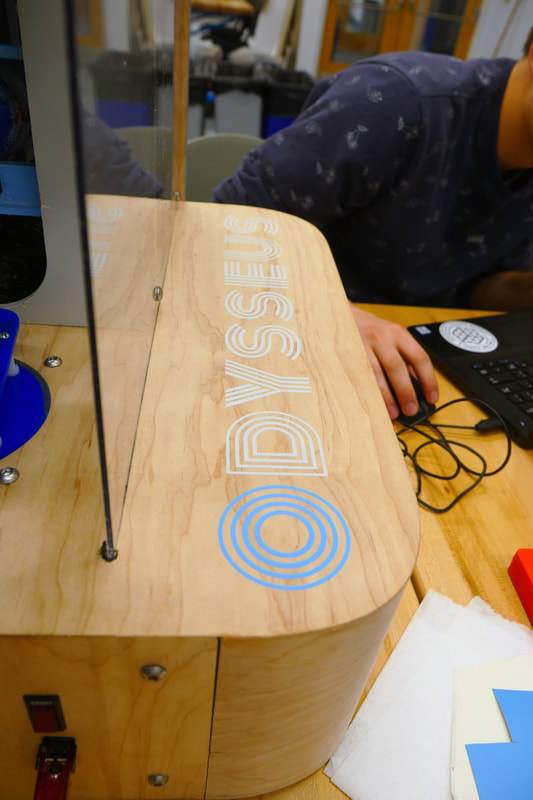
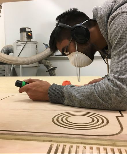
Of the many allowances for aesthetic functionality, the most interesting is our decision to develop curved corners on the housing's base. We opted to design our curves using an industrial design concept known as constant curvature (as opposed to standard circular curvature most commonly seen in Solidworks). This creates more attractive corners, and can be seen on virtually any curved product including computer keys, app icons, and phone screens. In order to fabricate the corners it is necessary to use a Shopbot CNC to kerf the plywood, carving deep parallel grooves to allow the 3/4" sheet of plywood to flex as if it was a thin sheet of veneer. This, combined with a 45 degree chamfer on all components, creats a curved housing with no side-grain exposed, a critical aesthetic point in our final configuration.
|
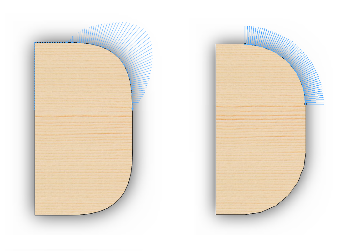
Demonstration of Continuous Curvature (left) versus a more standard Rounded Fillet (right). The radial lines at the corners represent intensity of curvature, with shorter lines indicating a larger radius of curvature (less rounded).
|
Cnc manufacture
|
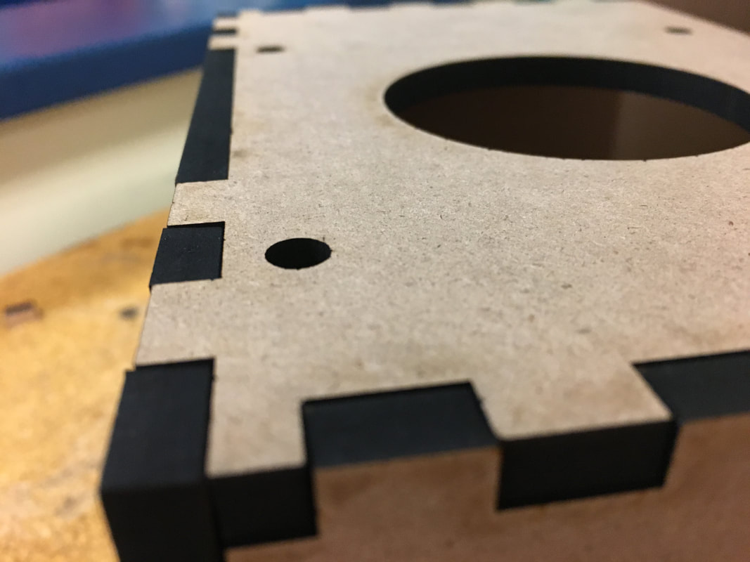
Using the Shopbot 4x8' Plywood CNC, we made the housing straight from the 3D part files that compose our Solidworks assembly. By first fully modeling each component, we ensured that everything fit together snugly and remained removable for interior access, a critical feature.
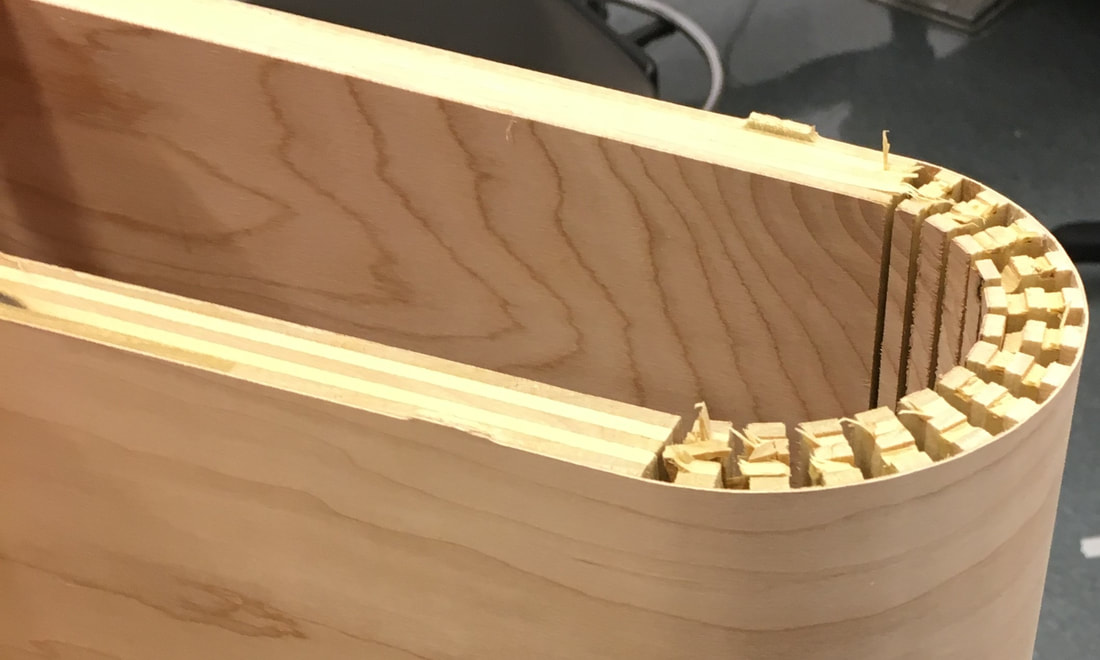
One equally important feature of the housing is the curved corners, made possible by the slotted plywood shown above.
|
Subsystem support
|
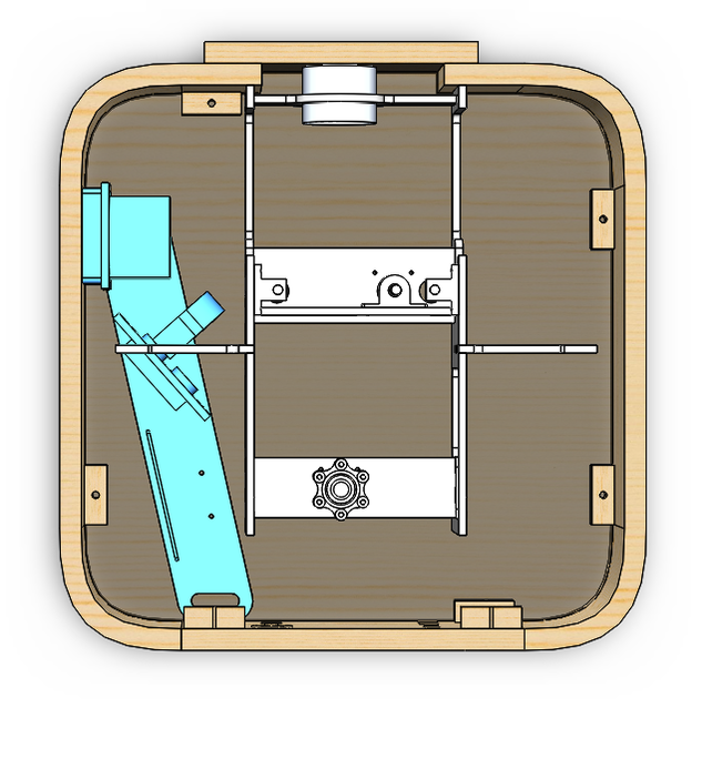
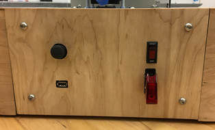
A critical aspect of the final product is the integration of the electrical and mechanical systems. To allow for that, we designed the Housing to have a removable electronics slide, which all critical components are mounted to for easy removal. This is highlighted in blue in the cross section taken at left. What makes this easy removal possible is the seperate control panel seen below. By removing this, we could reach in and modify the electronics, speeding the troubleshooting and polishing process significantly.
|
|
|
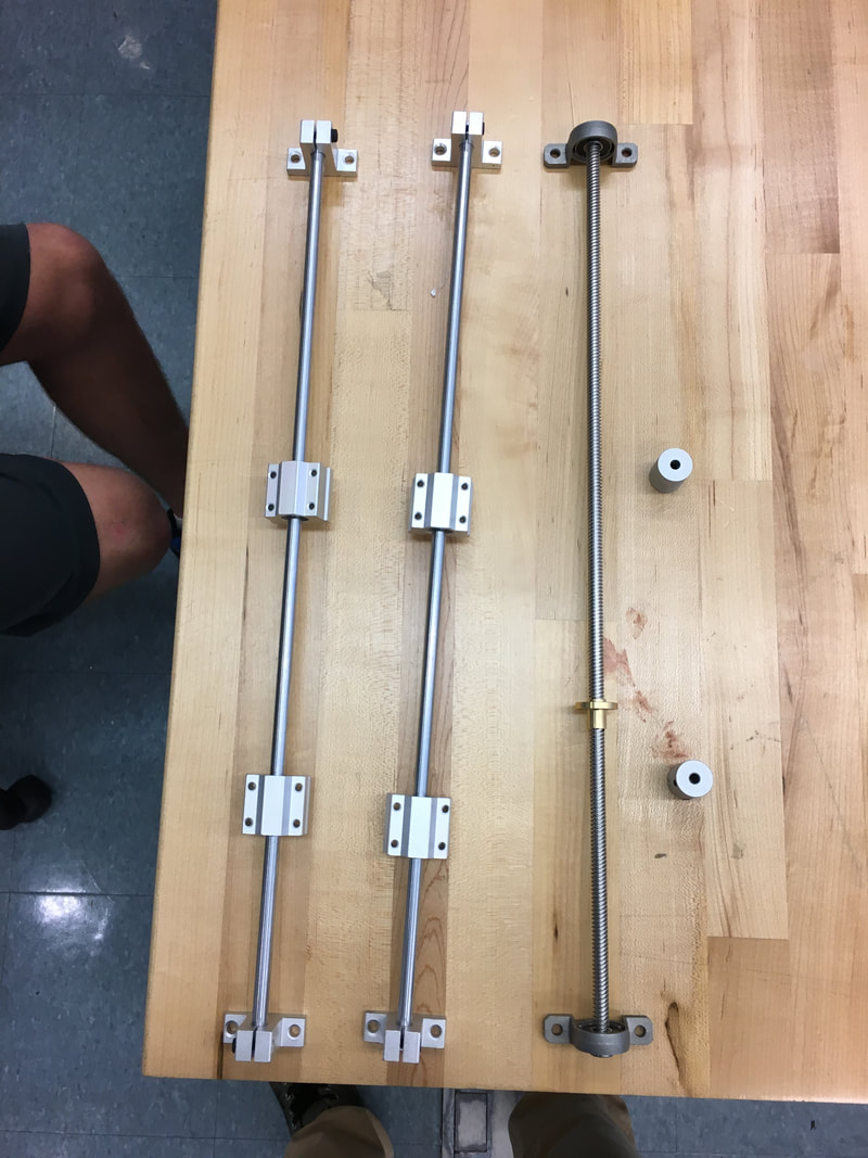
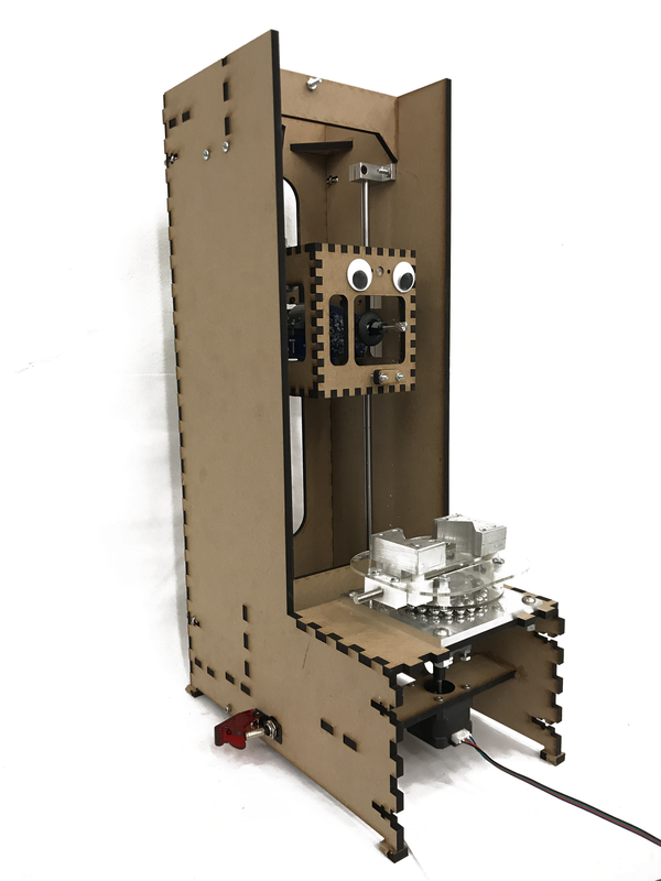
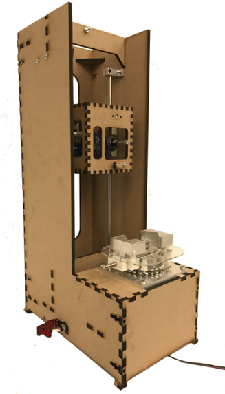
The central core of Odysseus is the upright MDF housing shown above installed, and as modeled. The most difficult aspect of the design of this framework was properly aligning the linear slide components, a tricky problem of under-constraining a system that would be over-constrained if firmly mounted. To alleviate this issue, we installed the full vertical slide assembly before tightening the vertical linear slides in place. In this way, we allowed the system to self-align, and only tighten it into place after we had proved that the desired range of motion could still be achieved.
Development of final iteration
Sprint One
|
|
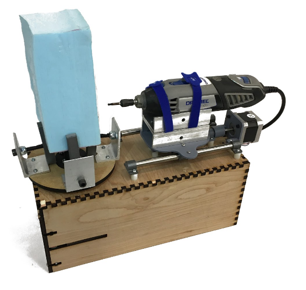
The whole process began with a vision of a functional cube-shaped assembly with a large hinged door encompassing the full cutting area. The first iteration of the physical assembly, however, was much less glamorous. Made out of 0.21" lasercut sheeting, this simple box supported the single stepper motor for the chuck, and the first iteration of the linear slide. Even though this was the very first sprint, our conceptualization of the final design was pretty fully formed. This was a good choice on our part, to fully define the system so that all work could be done to get to converge to that point. The first issues we encountered in this sprint was that of vibration, all of our fasteners were coming loose as the rotary tool vibrated with use.
KEY LESSONS:
- Define a target system early and well
- Fewer box joints are better
- Laser cutters are invaluable for prototyping
KEY LESSONS:
- Define a target system early and well
- Fewer box joints are better
- Laser cutters are invaluable for prototyping
Sprint Two
|
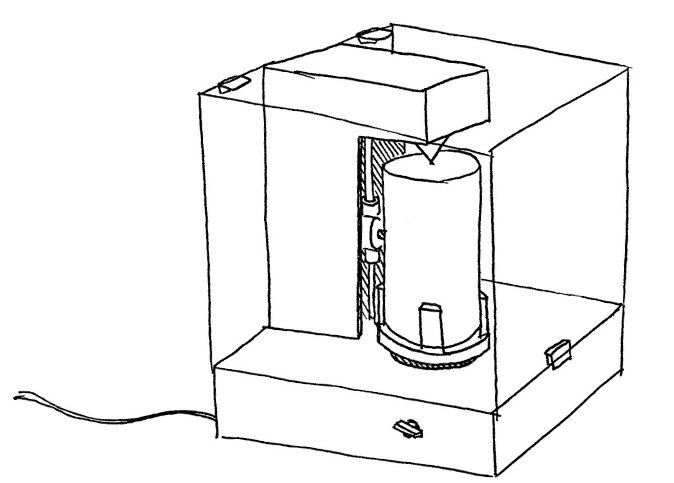
Sprint two brought a revolution in housing design with the addition of the third axis of motion. The upright portion of our design is beginning to take shape, although none of the electronics are enclosed, and as such there is no lower bulge to conceal those components. Additionally this is when the vacuum attachment first showed up in our ideation sketches, as seen on the rear of the project in the below sketch. At this point we had a functional mechanical system, but left a lot to be desired in terms of aesthetics.
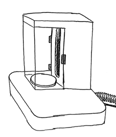
|
KEY LESSONS:
- Bolted connections are easy to make in MDF and less permanent than glue
- Oversize mounting holes for bought components, as their tolerances are often remarkably poor
- Focus on safety earlier on in the process
- Bolted connections are easy to make in MDF and less permanent than glue
- Oversize mounting holes for bought components, as their tolerances are often remarkably poor
- Focus on safety earlier on in the process
sprint three
|
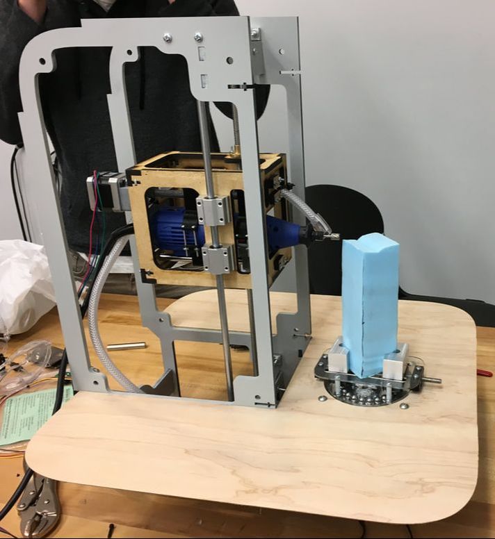
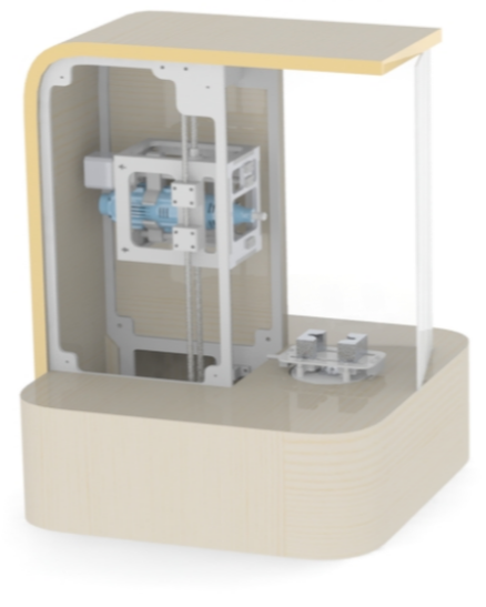
|
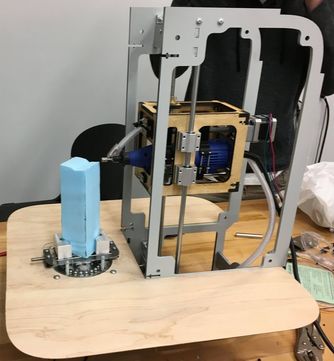
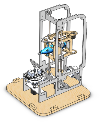
This is where the housing really began to take form. This sprint included the finalization of the cad for the housing (seen on the left, in remarkably close to final form factor), as well as the beginning of the manufacturing of the housing's key components. The first thing manufactured was the MDF frame, with all components installed on this to ensure a good fit. From there the top plate (seen in the right image) was made and installed so that the chuck could be operational to hit our Minimum Viable deliverable. At the end of this sprint we had attempted to cut the live hinged components twice, and failed at both attempts due to inexperience machining wood to such tight tolerances. As such we missed the mark on our minimum aesthetic goals, and would have to do a lot of extra work in the week and a half before demonstration.
KEY LESSONS:
- Allow more time than expected for manufacturing
- If cutting thin features on a shopbot, cut those first so that the wood moves as little as possible
KEY LESSONS:
- Allow more time than expected for manufacturing
- If cutting thin features on a shopbot, cut those first so that the wood moves as little as possible
Final push
Mechanically all that had to be done following in the week following the final sprint review was recut the housing components (more precisely the flexible housing components), bend the plexiglass, and assemble everything. This body of work was mostly done in the few days following the last sprint review, so that the electrical software integration could have more time to troubleshoot and debug.