CHUCK
fINAL dESIGN
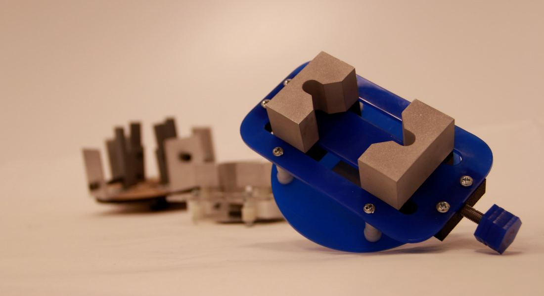
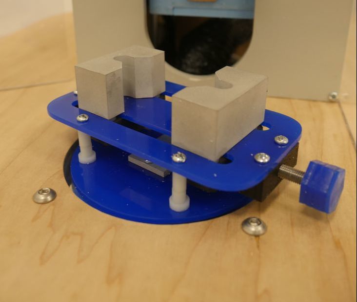
The chuck experienced 3 stages of significant redesign over the course of the project. Its final design was a turnbuckle-style actuation method and two 90 degree jaws.
Key Design Features
|
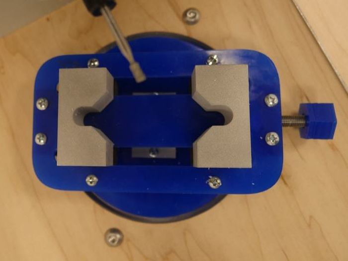
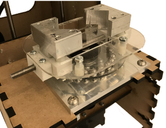
Turnbuckle-style actuation A custom-machined threaded rod is the centerpiece of the chuck's functionality. Half is left-hand threaded and the other half is right-hand threaded. The bottom of the jaws are tapped to match these directions, meaning that turning the handle of the rod clockwise brings both jaws together and counterclockwise separates them. This mechanism means whatever size part we use will be perfectly centered on the axis of rotation. |
|
|
Easy-to-use, secure fixturing The handle seals together two jam nuts tightened against each other. The hexagonal shape allows the user to comfortably adjust the position of the jaws by hand, but also ensure that the work-piece is securely held by fitting a standard 3/4" socket wrench on the handle. |
|
|
Reliable Rotation
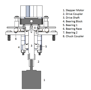
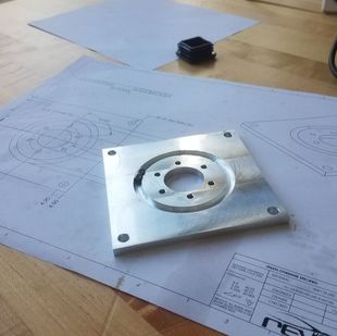
To be fully effective in the context of the larger machine the chuck needs to be driven by the z-axis stepper motor smoothly and reliably. This is primarily accomplished by a bearing race for the chuck to sit on and custom drivetrain from the stepper to the chuck. The bearing race is filled with 3/8" ball-bearings and was CNC milled into an aluminum plate that bolts into the housing. The drivetrain consists of a custom shaft, two couplers, and a stack-up of two bearings to ensure that the stepper can drive our work-piece consistently and reliably. |
|
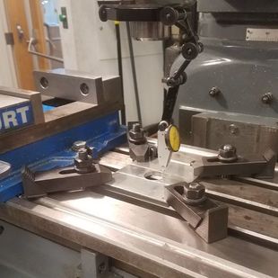
Precision Machining
The final implementation of the chuck contains all precision components. The jaws, couplers, bearing race, and drive shaft were all machined, many with CNC machines. All of the planar components were laser cut. All 3D printed components were done multiple times to hit tolerances, and our final pieces were made on a Markforged Mark Two printer for strength and accuracy. Making smart manufacturing decisions helped ensure easy assembly and no slop in critical areas - specifically clamping and rotating.
The final implementation of the chuck contains all precision components. The jaws, couplers, bearing race, and drive shaft were all machined, many with CNC machines. All of the planar components were laser cut. All 3D printed components were done multiple times to hit tolerances, and our final pieces were made on a Markforged Mark Two printer for strength and accuracy. Making smart manufacturing decisions helped ensure easy assembly and no slop in critical areas - specifically clamping and rotating.
|
|
Design Process
|
Version 1 Starting the entire project from scratch with a 2 week sprint meant we needed to move extremely quickly on design to get some sort of working option by the end of the sprint. The chuck finished sprint 1 with an extremely rudimentary design. The basics included four independently adjusted jaws. Our threaded rods were simply long bolts, and our axially constraint were locknuts. In the spirit of rapid prototyping we had drill-pressed L stock and 3D printed jaws. While this was enough to clamp our piece and understand the basic mechanics of the system. The bearings we bought, bearing blocks we 3D printed, and 3D printed coupler to the stepper motor ended up performing extremely effectively - and we re-used all of these components for every single future sprint. |
|
|
Version 2
The second version of the chuck increased the quality of design and manufacturing significantly. We implemented two 90 degree jaws that were coupled with a threaded rod - half left-hand threaded and half right-hand. This design lacked proper axially constraint and was very difficult to adjust. The jaws had a lot of issues - they were roughly cut, and when we tried to tighten hard, they would torque outward instead of providing a secure clamp. Our 3D printed coupler to the drive shaft was very bad - there were tolerance issues that we stop-gap solved with super glue and press-fitting was unreliable for our manufacturing methods. At the end of this design phase we were satisfied with the general mechanism, but recognized the need for targeted redesign and precision improvements. |
|
|
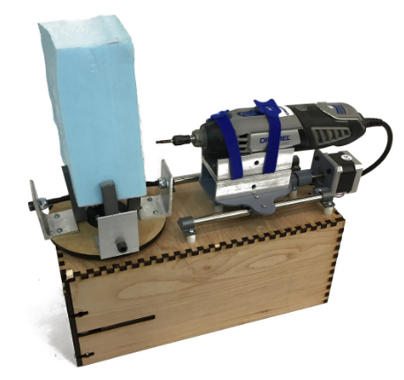
Version 3
In the final chuck we machined a new shaft out of aluminum with precision alignment and coupling features. A matching coupler was milled which was screwed into both the shaft and rotating plate for alignment. This fixed our issues with wobbling and slop. The final jaws were CNC milled so that they were identical and with exactly 90 degree angles to center the stock being clamped. The piece underneath the jaws that the threaded rod screwed into was attached to the jaws at 4 points to ensure the jaws could provide significant clamping force without bending outward away from the stock. Finally, with an eye on aesthetics for our final design, we used opaque blue acrylic, all black 3D printer filament, and sand-blasted aluminum. |
|