Electrical design |

|
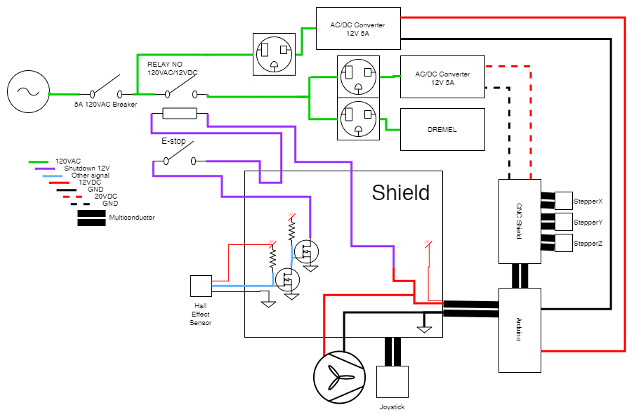
BLOCK DIAGRAM
SYSTEM REQUIREMENTS
SAFETY
In order to guarantee safety, we included a shutdown circuit which controls our main AC relay through our low voltage system. We implemented two power stages in series, a mechanically actuated toggle switch and magnetic door switch, such that either could independently interrupt current to the relay and immediately shutdown all moving components in our project. As can be seen in the block diagram, the toggle switch directly opened the shutdown circuit while we incorporated the magnetic switch as a trigger through an inverter to a low side drive transistor.
Furthermore, we practiced professional wiring practices to fabricate our fully enclosed electrical system. This included proper shielding and strain relieving of all electrical connections to prevent system failure and shorts. Additionally, a custom PCB shield prevented soldered connections and improved our wire routing while allowing us to access more pins on the Arduino and still connect to our CNC shield. As a result of our wiring practices, we developed a robust, fully enclosed system which has had no failures and required no maintenance giving us confidence in testing our mechanical systems and firmware.
Furthermore, we practiced professional wiring practices to fabricate our fully enclosed electrical system. This included proper shielding and strain relieving of all electrical connections to prevent system failure and shorts. Additionally, a custom PCB shield prevented soldered connections and improved our wire routing while allowing us to access more pins on the Arduino and still connect to our CNC shield. As a result of our wiring practices, we developed a robust, fully enclosed system which has had no failures and required no maintenance giving us confidence in testing our mechanical systems and firmware.
AESTHETICS
Our electrical design complemented the overall aesthetic considerations made by our mechanical team. In our final design, the entirety of the visible electronics included a C14 panel mount plug in the rear and a switch, breaker, programming port and joystick on the control panel. Additionally, all visible wires were enclosed in wire sleeving and inconspicuous. Our internal power electronics allowed us to route and control our AC power in an entirely eclosed system giving the professional visual of a simple power cable as the only externally visible electrical component.
MACHINING
Our electrical system utilized a CNC shield V3.0 along with 3 Pololu A4988 motor drivers which gave us independent control of all three axes driven by our stepper motors. Addtionally, a control panel mounted joystick allowed a user to manually control the two linear axes in order to zero them before beginning machining. One learning experience in our electrical design process came when we fried our electronics due to overdrawing current when putting our steppers under a heavy load. We prevented this issue in the future by properly setting the current limit on our motor drivers. For redundancy we also reduced the loads of our machining by taking smaller passes and implemented proper circuit protection.