Horizontal Slide
Final Design
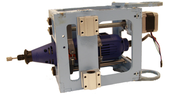
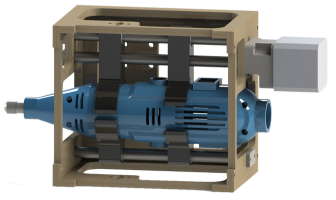
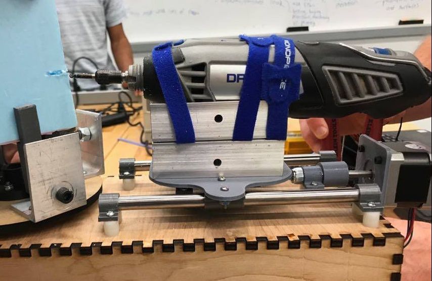
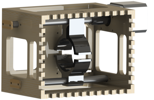
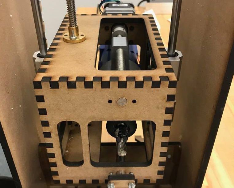
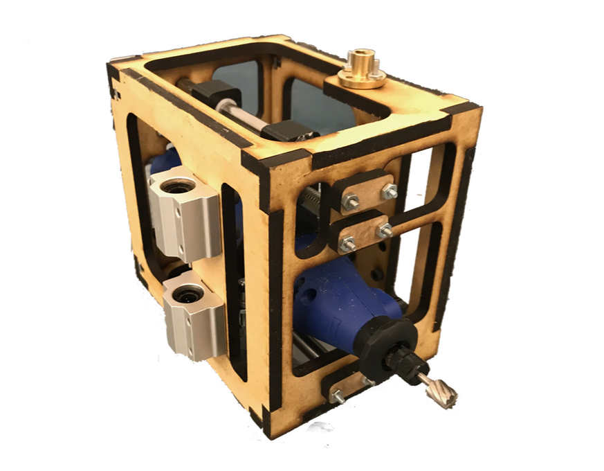
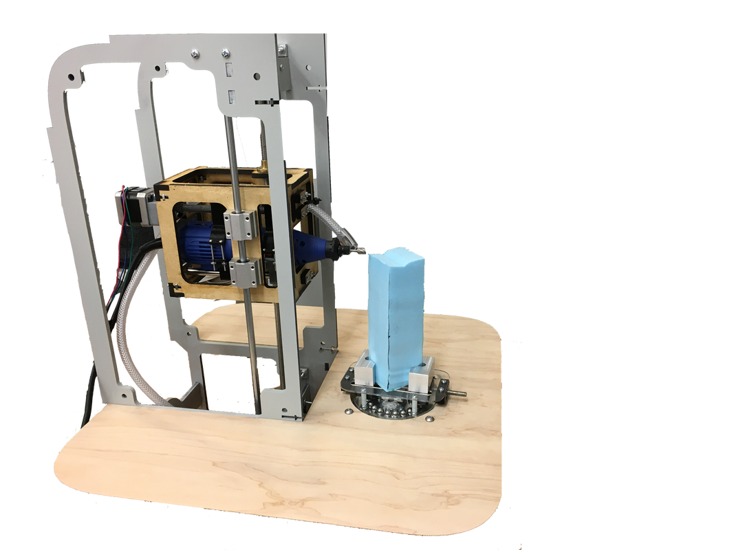
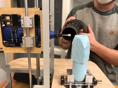
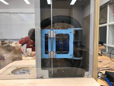
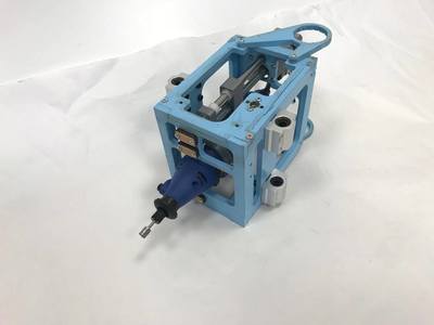
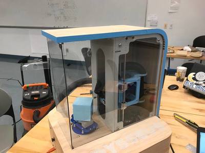
The horizontal slide is one of the central systems of Odysseus. It rides along the vertical rods of the housing and, while doing so, provides horizontal movement for the cutting bit. Comprised of an MDF frame, the horizontal slide is driven by a vertical threaded rod and guided by 4 linear bearings. Internally, it houses the dremel in a secure way using 3D printed mounts and is connected to 3 horizontal rods: one threaded. The dremel mounts include Delrin spacers which ride on the top and bottom steel rods. By including two rods, the rigidity of the dremel bit is significantly increased. By turning the motor, the threaded rod spins and drives the dremel forward as the threaded rod moves inside of a tapped PVC piece. This robust system successfully holds the dremel while providing significant amounts of travel in the horizontal direction. We took the knowledge from each successive sprint to put together our final design. Each sprint, we analyzed the problems and advantages of the previous design to create the best possible final product.
Final Design Features
|
Increased Mounts:
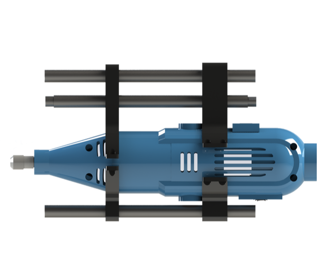
This iteration of our slide includes two non-threaded rods and two sets of dremel mounts. This was updated from previous iterations to better secure the dremel within the assembly. |
Slotted Mounts:
In this iteration, the bottom 3D printed pieces were slotted. These mounts still rotationally constrain the dremel, but the slot allows the mounts to slide easily, reducing the friction of the overall system. |
Vacuum Mounts:
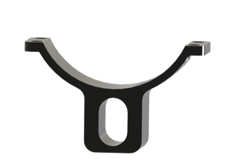
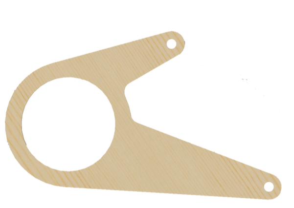
In order to secure the vacuum to the assembly, we laser cut removable mounts that could be attached to our housing. The mounts allowed the vacuum to be easily moved to the correct position. |
Motor Mount and Coupler:
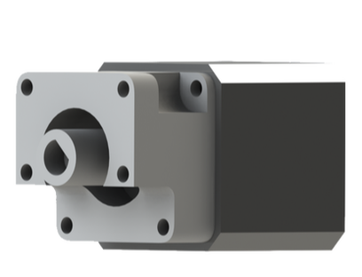
We created a new 3D printed piece to couple the threaded rod and motor shaft together. Also, a new motor mount was created to move the motor away from the housing, increasing travel. |
Progression to Final Design
Sprint ONe
|
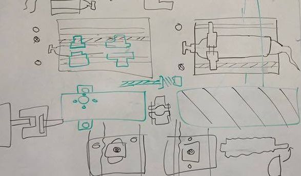
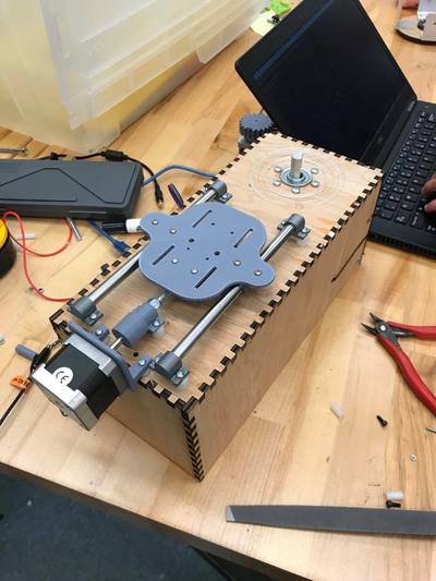
Much of the first sprint was comprised of designing the overarching horizontal slide. The main goal for the first sprint was to create a proof-of-concept horizontal slide. Because of this, the first slide included a 3D printed deck driven by a 1/4-20 bolt coupled to a stepper motor. When the stepper motor turned, a 3D printed piece connected to the threaded rod was forced to move forward and backward. For this sprint, the 3D printed piece had a tapped hole which allowed the threaded rod to drive it. The deck included two more 3D printed mounts which rode along steel rods. Little consideration was given to the mounting of the dremel or the frame of the slide because it was not necessary for the proof of concept. Because of this, the horizontal slide for Sprint One was not its own assembly but was integrated onto the top of the first housing. This first iteration was able to move forward and backward along the x-axis under its own power. Of course, this first iteration certainly had its problems. It lacked travel, was extremely stiff, was misaligned, and was, overall, a wreck. However, it served as a perfect proof of concept that pushed further development in Sprint Two.
|
Sprint Two
|
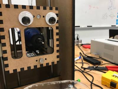
During Sprint Two, the majority of the focus was placed on converting a proof-of-concept system to a stand-alone system. Namely, a frame for the dremel and dremel mounts were designed and printed. The second sprint included an MDF housing that was laser cut and glued into place. This housing included many finger joints to create an extremely rigid housing. For this sprint, the dremel was contained with two 3D printed mounting pieces. The top mounting piece was tapped so it could be driven by a threaded rod. One threaded rod was mounted above the dremel, and another non-threaded rod below. The theory behind this was that by reducing the number of rods, there would be less contact force and less friction. Unfortunately, by having only one guide rod, the system encountered significant amounts of friction when accelerating. Additionally, based on the idea that the threaded rod would be overconstrained, the 3D printed coupler was swapped for a flexible coupler. By the end of Sprint Two, this system was able to successfully stand alone as its own system. It fully integrated the dremel and provided forward and backward motion along the horizontal axis. However, this encountered even more friction than the previous sprint's system, making reducing friction a main goal for the horizontal slide during the third sprint.
|
Sprint Three
For Sprint Three, the goal was to successfully fix the friction issues encountered by the previous slides. To accomplish this goal, the sprint started off with a redesign based off of last sprints problems. The team concluded that the previous slide had large amounts of friction because it only had a total of two rods, had slop in its 3D printed components, and had friction between the end of the threaded rod and the housing. To solve these problems, the new housing was expanded to include another rod and included a bushing at the end of the threaded rod to decrease friction. The system was then assembled, but still had significant amounts of slop. This drove a phase of iteration and testing to fix the slop inside the slide. A variety of fixes helped reduce the slop, including machining Delran spacers that fit into the 3D printed mounts to reduce friction, but two fixes stood out as the most influential. First, the bushing at the end of the threaded rod was removed, allowing the rod to free-float. The threaded rod was not properly aligned, so removing the bushing stopped it from being over constrained. Lastly, the holes in the bottom 3D printed pieces were converted to slots. This allowed the horizontal rods to slide, not rotate, reducing friction without compromising stability. At the end of the Sprint Three, the horizontal slide was complete. As a standalone system, it fully accomplished our goals while being smooth, quiet, and easy to assemble. Only by drawing on the knowledge from the first two sprints were we able to bring this system to realization. After the third sprint, the final iteration of the horizontal slide was started. The new housing added slight modifications to create a finalized product that was both functional and aesthetically pleasing.

