Sprint 3
Weeks 5-6
Sprint Overview
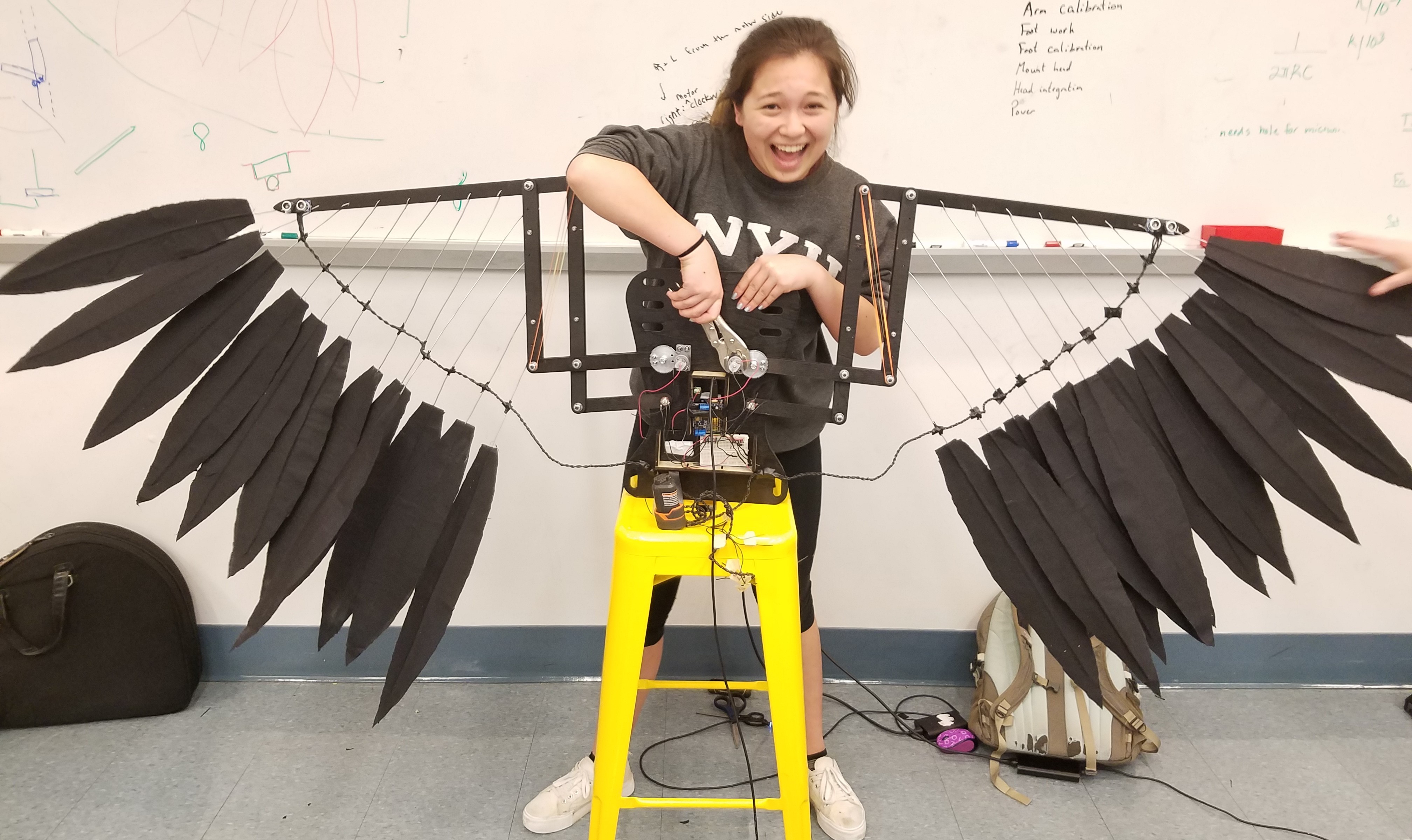
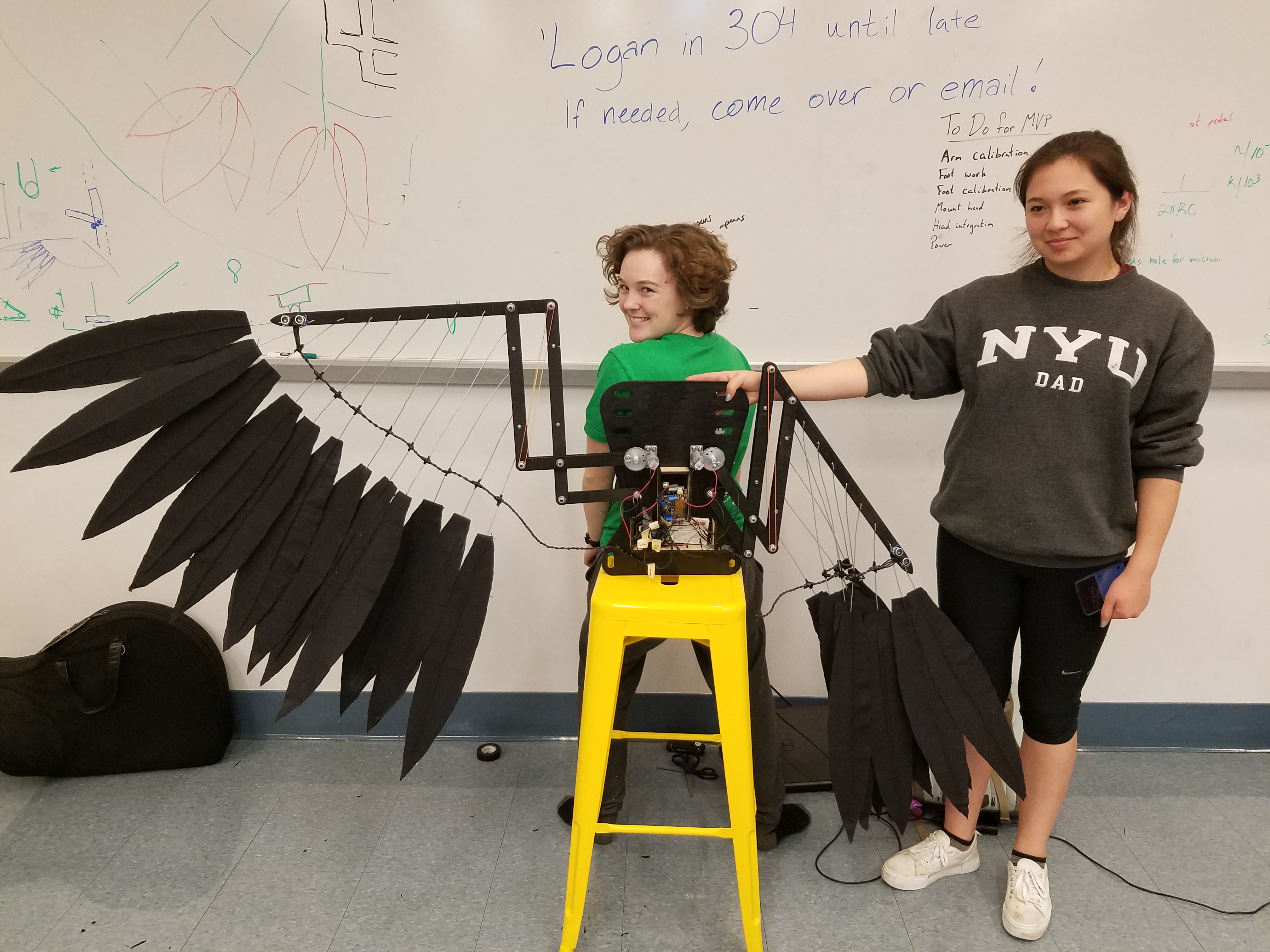
In this sprint we made our final linkages and incorporated feather mounting holes as well as spacer points to add strength. We integrated our linkages with our electronics boards and attached all of these to the backboard. We incorporated position control and added several different wing motion modes.
Backboard
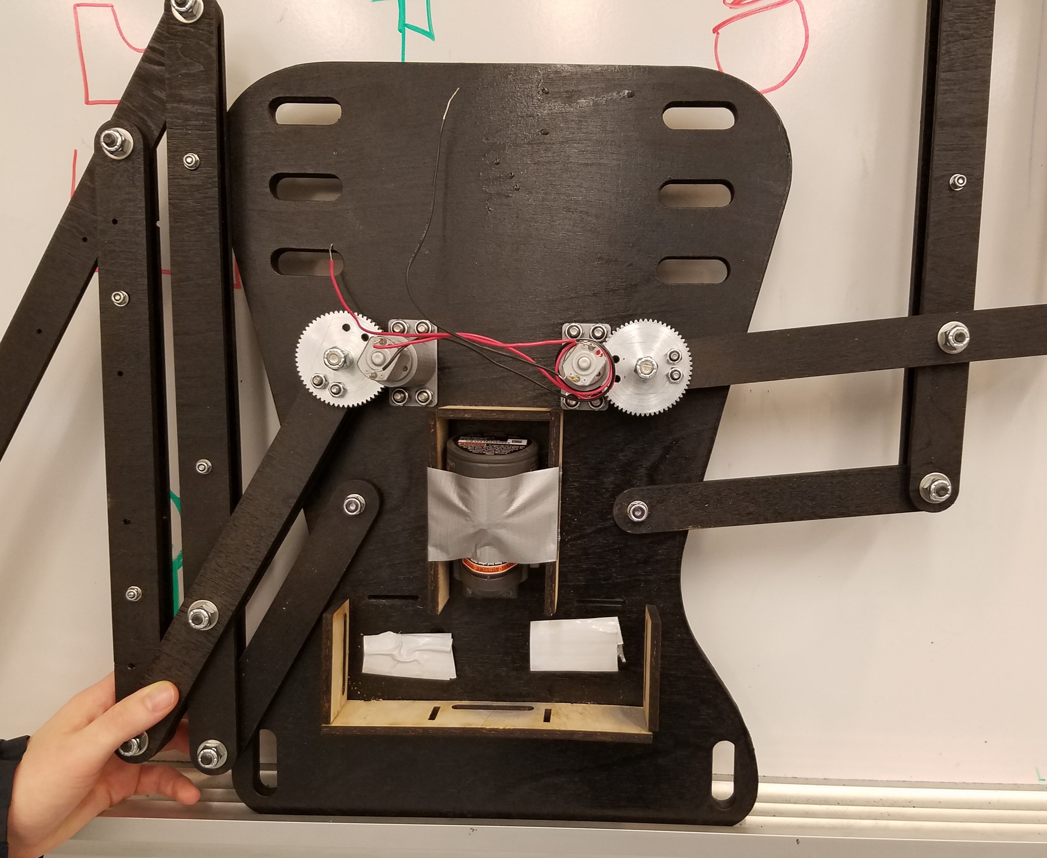
We created a detailed CAD of all attachment points on the backboard so that there wouldn't be any unforeseen conflicts. This included slots for the electronics box, mounting holes for wings, and slots for harness. We then shopbotted the board in an elegant form.
Harness
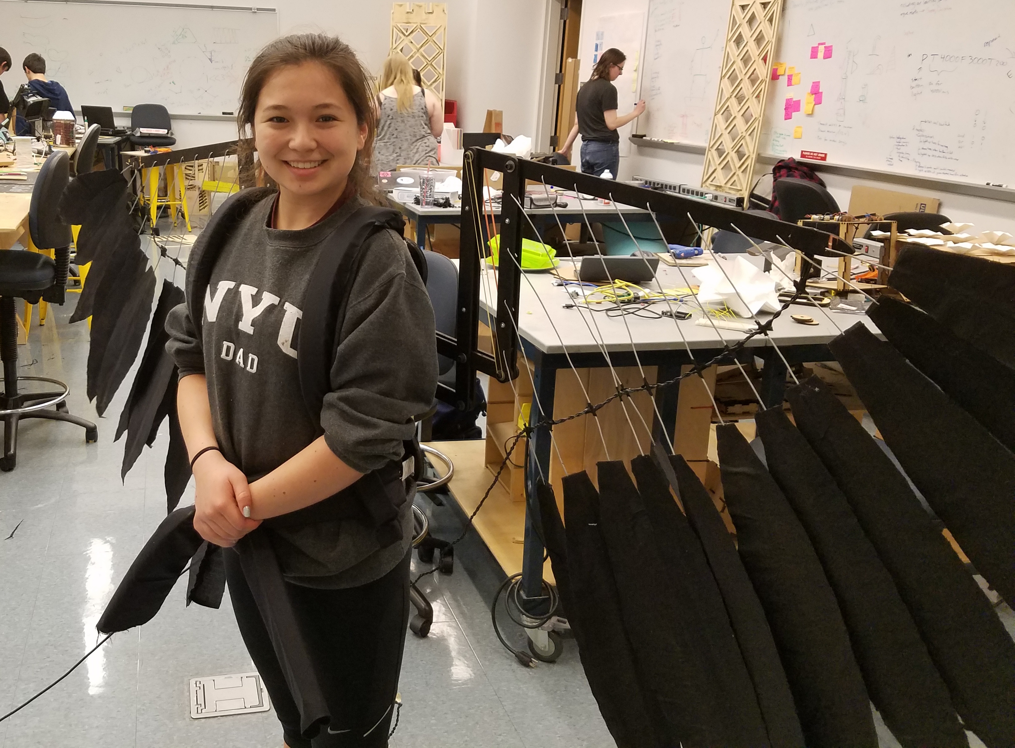
We sewed shoulder and waist straps out of cloth and foam and connected straps to the backboard with velcro. The shoulder straps were adjustable for torso length and shoulder size while the hip straps were adjustable for waist size.
Actuation
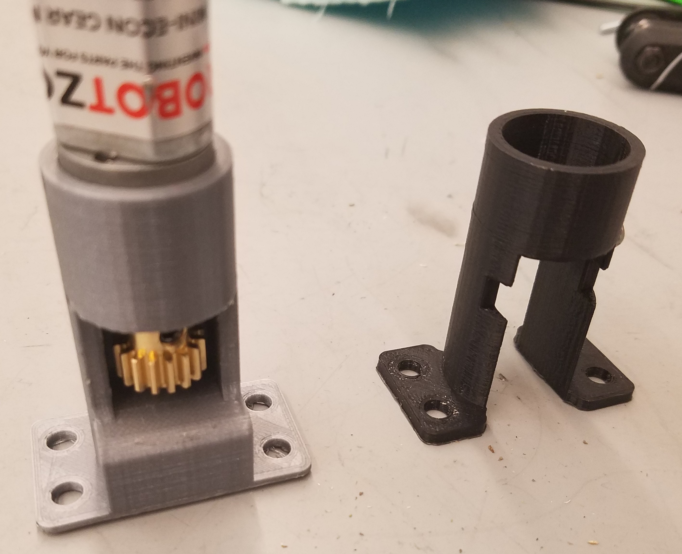
Detailed CAD allowed for precise alignment of gears and motors. Our first motor mount that we 3D-printed wasn't strong enough and cracked. We believe this was because of the force of the torque being translated through the motor into the mount. We worked on this over several mount iterations that were increasingly sturdy.
Feathers
We created full scale prototypes of our feathers and attached them to our linkage wings. We were able to model the placement of the feathers in CAD so that each one had a specific wire length that allowed the overall spread of feathers to be a smooth arc. These ended up being 14" long and a series of 12 feathers on each wing.
Software
In sprint 3, we switched from Infrared sensors to ultrasonic sensors, because of their price. We incorporated the ultrasonic sensors to serve their purpose of obstacle avoidance. Ultrasonic sensors send an ultrasonic ping and wait for a response, and the response time is proportional to the distance of objects. We realized that the default timeout for the sensors was very long, but we were able to cut it down because our use case only cares about very close objects, which would have a very small response time.
Flex Sensors
Preliminary testing of flex sensors showed that they worked, and we were able to map a flex sensor value to an angle. We decided to table the calibration for this time because we needed a physical cuff to know our exact maximum and minimum values.
Potentiometers
We attempted to attach the potentiometers physically to the wings, but because of mechanical problems with our far from ideal potentiometers we had a hard time getting them to move consistently in the way we wanted, which made testing difficult. We did, however, attempt to map the range of potentiometer values to a range of wing angles. This was less than ideal because our potentiometers at this time were on a logarithmic scale, but we wanted to map it to a linear difference in angle.