Sprint 1
Weeks 1-2
Sprint Overview
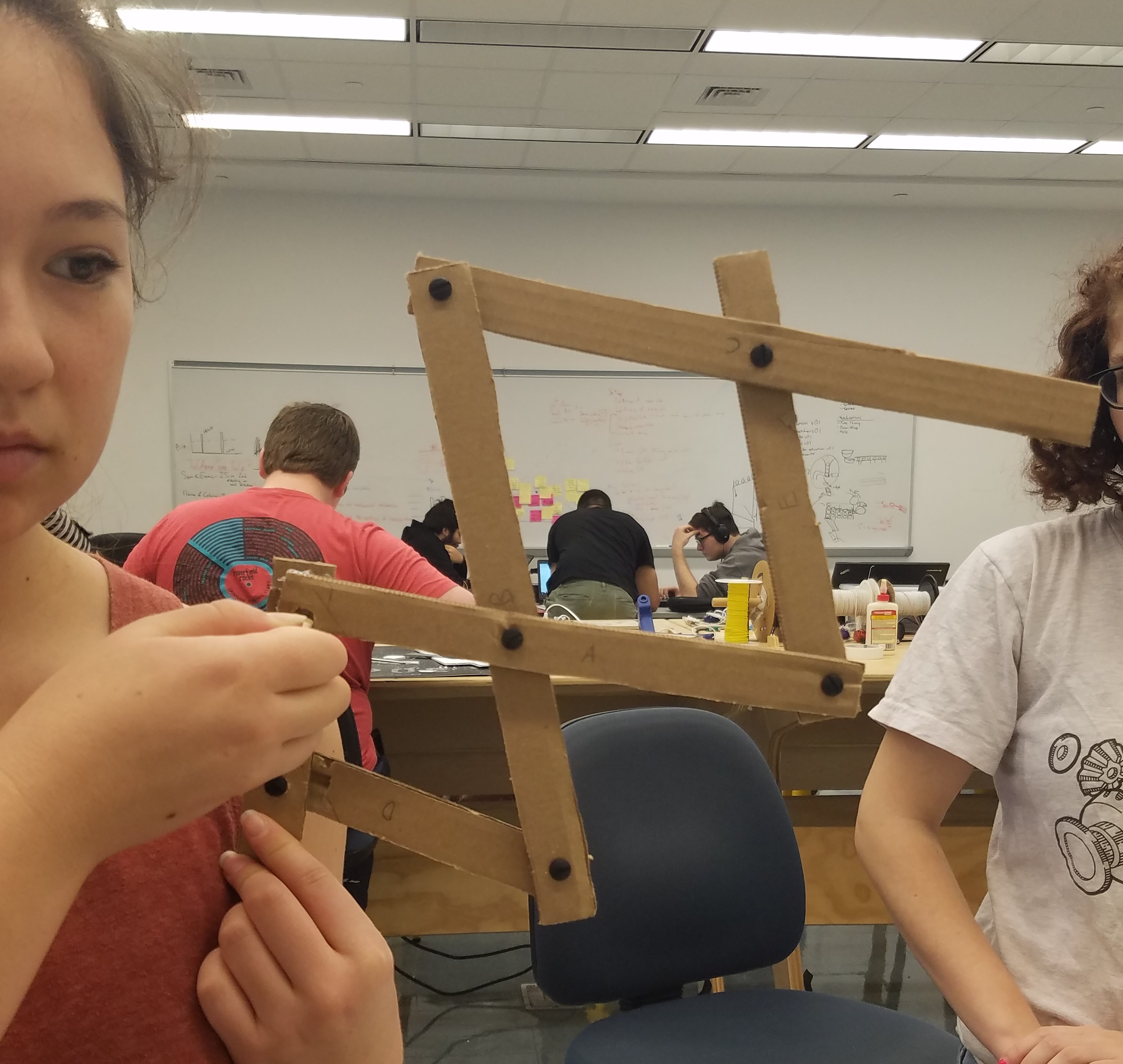
In our first sprint, our goal was to make a small scale, integrated sketch model of a wing. This included an infrared sensor (borrowed from the POE studio), a cardboard linkage system, and a servo (also borrowed from the POE studio). We were able to get the wing to flap, and stop when we detected something close with the IR sensor.
Linkage Geometry
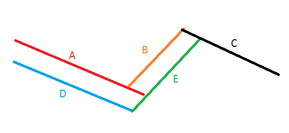
We researched different linkage stack ups (number of bars, pivot positions, etc.) and modeled these configurations in CAD. We created relations such that the linkage lengths could be modified on one model (on the right in the image below) and a second model (on the left in the image below) would have equal lengths and could be fixed to pivot about a point to simulate the wing opening motion.

Using this geometry modeler we were able to create a scaled CAD model and adjust it to fit well onto the back of an average sized person. These linkages were fixed at the physical mounting points and configured in the open state, the collapsed state, and a floating state where the motion could be manipulated.

Software/Electrical
We hooked up an IR sensor to the end of the wing and the servo to the base. We wrote a code that moved the servos, which flapped the wing up and down, except if something was in the path of the IR sensor, in which case it stopped where it was and started going down. We found that using one distance sensor did not account for all the directions that we want to be able to see, so we decided that in future iterations we would use two per wing, and have one additional one facing forward as well.
Problems Identified
Sometimes when the wings extended, the sensor wires became disconnected.
Some of the bars were 'woven' together leading to increased friction.
Even the small scale prototype had flexing issues.
The sensor on the end did not face out the entire time. This interfered with sensor effectiveness.