CNC Gantry
How the thing moves.
Iterations
The team went through many different gantry designs before settling on a final version. One of the team’s major goals at the beginning of the project was to get better at the integration of mechanical subsystems and to effectively iterate from sprint to sprint. We different gantry designs, optimizing each one for performance. We used the lasercutter in Olin’s machine shop to effectively rapid prototype, leading to a refined and robust final product. Assembly consisted of attaching the laser-cut components together, fitting the extrusion components into the model, connecting the drivetrain components, and installing the timing belts. While lasercutting the entire model took about an hour, assembling everything together required 5-6 hours (or 20-24 person-hours).
Version 1
We designed the first version of our gantry to conceptually satisfy the desired 2-axis functionality
This design, with the pulleys of the short axis rotating about a vertical axis, required the guide rods of the minor axis to be positioned further apart than the width of the squeeze bottle. We found the resulting model to be much heavier than believed would be able to be pulled by a belt for movement along the major axis. Although one axis worked well, once we discovered that we had designed this crucial structure to be much too heavy, we decided to go back to the drawing board.
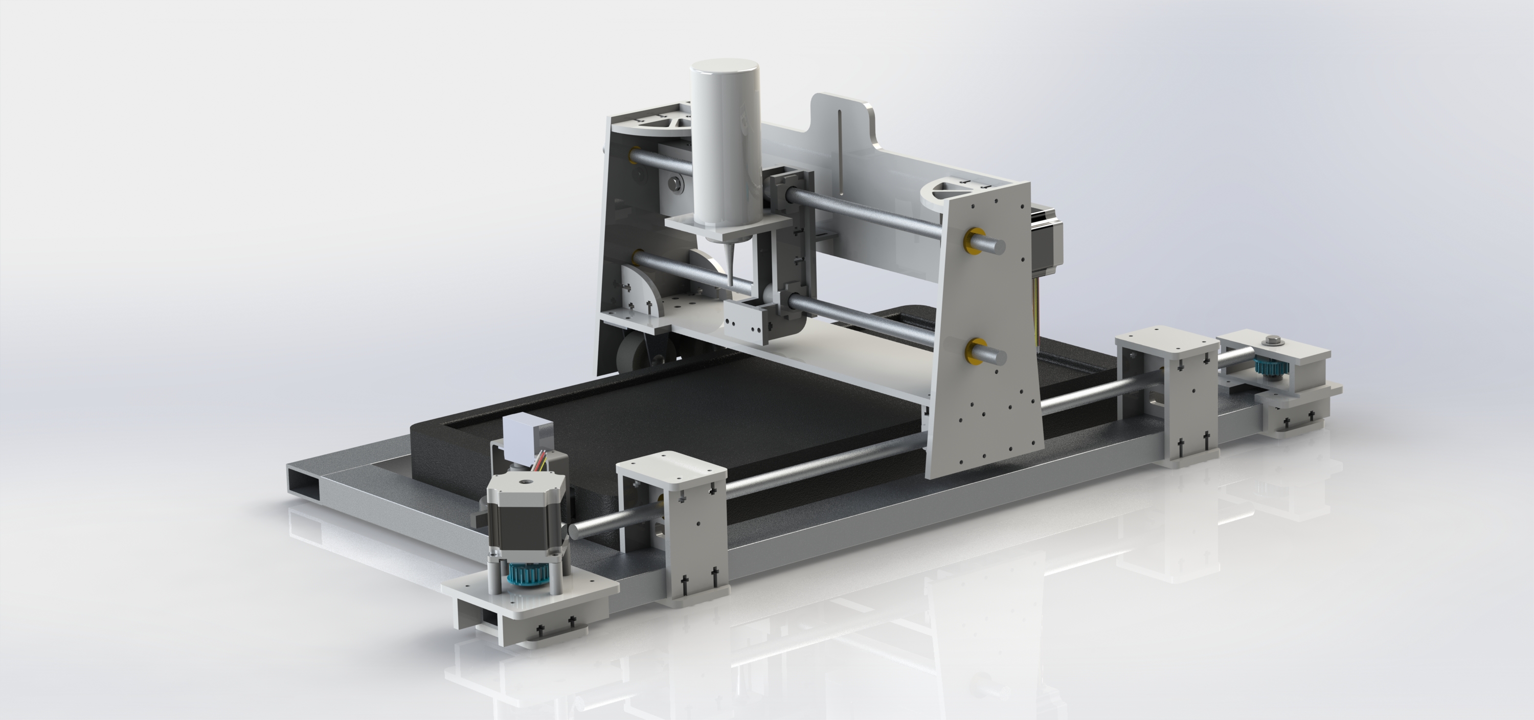
Version 2
After constructing Version 1, we realized that we could alter the design so that the pulleys could rotate about a horizontal axis, allowing us to design a much lighter and slimmer structure in which the guide rods would be stacked vertically:
Unfortunately, this iteration was no magic fix to our problems. We had been so weight conscious in the design of this model that we overlooked its structural rigidity. As the model relied on our Teflon bushings being completely parallel to each other, the smallest amount of flex caused complete friction lock in the major axis. However, we were happy to see that the minor axis functioned well after such a drastic change.
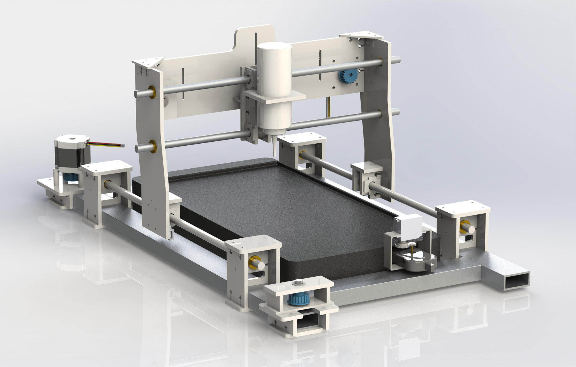
Version 3
Luckily, Version 3 solved all of our problems with two major changes:
To improve the rigidity of the carriage, we added a low bracing piece. This removed most of the flex that we experienced in the previous design iteration. In order to completely prevent friction lock, we went further and replaced a guide rod on the major axis with two caster wheels that we purchased from The Home Depot. While we initially had reservations about using caster wheels (for fear of flex or bounceback), trying them out yielded positive results.
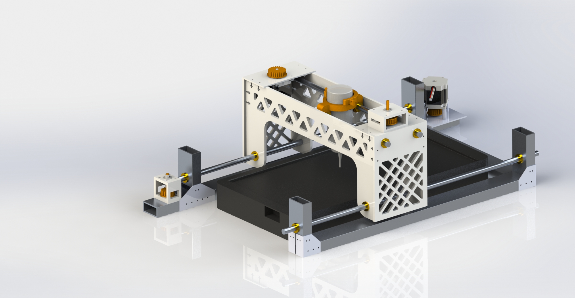
Final design
Since we had time to design and fabricate one more iteration, we took the time to improve the visual appeal of some of the parts by adding fillets and removing some of the features we had added for the convenience of prototyping (such as extra slots). We also slightly modified a few pieces to include holes into which limit switches could be installed.
Additional note: We designed and laser-cut an entirely different Version 3, concurrent with the model above, in order to better ensure that we would have 2-axis functionality by our third sprint review. This model elevated all of the components on the major axis so that the major axis guide rods could be placed as high as possible, allowing the carriage to be much lighter. However, when we discovered that our first design was successful, we decided to go with it and abandon this revision.
Structure
When designing the gantry structure, we had a few design goals in mind. We wanted a rigid structure that would provide a good base for driving our extruder and a design that would allow for every part to be interchangeable. With a design process focused on iteration, we wanted to be able to quickly swap in new parts if we found out a particular design didn’t work out.
To achieve these goals, we made main structure out of a combination of quarter and eighth inch MDF and hardboard. Most of the main gantry elements were made out of quarter inch pieces, while spacing elements were made of out eighth inch material. Pieces were connected with screw-reinforced mortise-and-tenon joints, as shown below.
The reinforced design of the gantry and the secure attachment method made the gantry both rigid and very easy to change. We used square nuts and 6-32 phillips head cap screws, which made it very easy to detach parts but when everything was fully tightened, we were left with a rigid gantry structure.
The main side rails consisted of long sections of 1 by 2 inch 6061 Aluminum rectangle tubing. We designed MDF pieces so that we would have a standard mounting system that would also allow us to take on and off the upper gantry structure. We wanted the entire system to be modular, so that we would be able to make small modifications as time went on and to make assembly easier. The modular mounting system also allows the gantry to be serviced and repaired more easily if the need arises.
Drivetrain
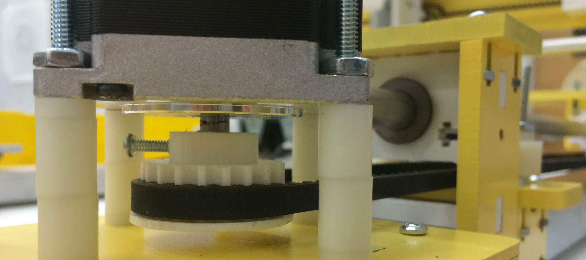
We elected to use an open belt system for our gantry due to its simple design and the relative ease for which we could manufacture parts to implement it. A belt system also would be less expensive and generally be able to be driven faster than a lead screw design. We found CAD models online of pulleys, modified them to fit well onto our stepper motor shafts, and 3D printed them on the Makerbot Replicator 2 printers in Olin’s library. We purchased HTD 5mm belt and attached each open end to the driven part of our gantry for both the major and minor axes.
To enable the gantry to run more smoothly, we added two wheels on the non-driven side of the major axis gantry. These were simple caster wheels purchased from Home Depot. This design change allowed us to drive one side smoothly and have the other side easily follow along.
We also developed a tensioning system for the belts on each of the axes of the gantry. This consisted of a slot, where we mounted an idler on a lot, forcing the belt inward. The idler consists of a delrin bushing assembly on a bolt, which enables the tensioner to rotate as the belt moves by it and also for the belt to slide easily on the idler if for some reason it fails to spin. We wanted to create a tensioning system that added little to no friction to the drivetrain.
To power the drivetrain, we used two Anaheim Automation High Torque Stepper Motors, one for each axis. We used the Adafruit Arduino Motor Shield (v2.0) to control each of these. We used some Igus Energy Chain to help route the many wires coming off of the gantry.