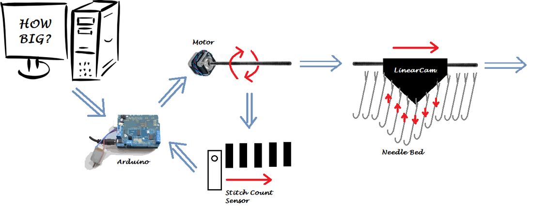
Current System Diagram
In brief, our system functions as follows:
- Using a graphical user interface in python, we set the length and width of the desired scarf. This information is sent to the Arduino. The Arduino the auto-homes the carriage using a limit switch, a DC motor, the Adafruit motor shield.
- We thread the machine and cast on the correct number of stitches starting from the far right.
- Once homed, the Arduino turns the motors on.
- The motor turns a thread rod which in turn translates the carriage linearly across the needle bed.
- Within the carriage is a linear cam which actuates the needles as it moves over them.
- The in-and-out motion of the needles, combined with a verge and weight comb as constraint on the fabric (see needle section of page), causes the yarn to form stitches .
- Meanwhile the IR sensor is moving with the carriage over the sensor bar. The sensor data is returned to the Arduino and is used to count the number of needles that have passed.
- Once the correct number of stitches (as given by the sensor bar) is achieved, the motor reverses direction and the process is repeated until the correct number of rows have been created.
- The motor turns a thread rod which in turn translates the carriage linearly across the needle bed.
- We manual bind off the stitches from the needles.
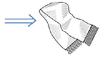
- Scarf
Needle a Bed to Sleep
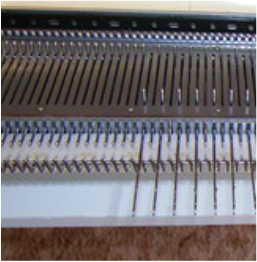
The needles are constrained by slots in the needle bed which allow forward motion without letting the needles wobble from side to side. Because the slots need to be relatively frictionless and precisely-sized, we elected to laser cut the needle bed out of acrylic.
The slots are designed to be long enough for the needles to fully pull through a stitch. Commonly in needle bed there is extra space in the back for the needles to moved in line with different stitch channels in the linear cam or deactivated by moving completely behind the carriage's path. We plan to actuate only one type of stitch--the knit stitch. However, we do need to be able to deactivate needles in order to vary the size of the scarf produce.
Moving the carriage a varied distance is insufficient. The carriage will start to knit a stitch on any needle it passes over and it must completely pass over a needle to finish a stitch. When the carriage has finished moving the width of the desired scarf, the carriage will have started to knit stitches on some of the needles in addition to those wanted for the scarf. Because of this a deactivation location or other means of deactivating a stitch is necessary. Ideally we could like to use a second channel and motorized channel switcher in the cam to deactivate and activate needles as needed. First, we will start with the simpler model of having a deactivation position in the needle bed.
Our Build:
- Needle Bed: Laser Cut Acrylic
- Slot Positions/Length: (1) Knit Stitch and (2) Deactivated
Cam-pletely Comprehending the Carriage
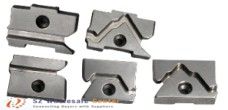
Needle motion is actuated by a linear cam moving perpendicular to the needles. A vertical cam follower on the top of each needle protrudes above the surface of the needle bed. The desired motion of the needles is a smooth, consistent forward motion followed by a smooth consistent backward motion. The needles do not need to pause at any particular points nor reverse direction save once. The simplest channel shape to create this motion is is a V-shaped channel. To avoid discontinuities in the channel, which might cause the needles to jam or get stuck, the channel end will be rounded off to form a tangent with the direction of the incoming needle follows,. Additionally the point of the v-shaped channel will be round. As the cam passes over each needle, the needle follows the angled surface of the cam forward and then back again. As we are only actuating one type of stitch, only one channel is needed.
The distance between the top and bottom of the channel must be large enough for the needle to pull all the way through a stitch. We believe this distance to be the length of the needle head to the end of the open latch. We will additionally add space for the thread to completely clear the needle head and latch. A cam that is too wide is unwieldy and activates many needles at once causing additional power to be supplied by the actuator. Additionally more space is needed on either side of the needle bed for the cam to completely pass over the entire needle bed. A cam that is too narrow causes the cam channel to be steep and difficult for the needles to move along to to friction and force direction. Commercial at-home machine typically use between 5-10 needles in the carriage at once. As out machine will be much smaller than normal machines (50 needles as opposed to hundreds) we are opting for a 5 needle carriage. yarn guide
Carriages also include a yarn guide to correctly place the yarn over the needles. Commercial machines also include tension adjustment knobs to accommodate different types of yarn . The tensioner ensures that the yarn fed in is kept in sufficient tension to not slip off the needles but not so much tension as to restrict needle motion. We additionally wish to use two colors in our pattern and thus require a way for the colors to only be fed into the needles one at a time. We plan to integrate this feature with the yarn tensioner.
Our Build:
- Cam Shape: Single Rounded V-Channel (Changed to Include a Single Straight Deactivation Channel)
- Cam Follower Displacement: 2.5cm (Changed to 3.5)
- Carriage Width: 5 Needles (Changed to 12)
- Yarn Guide: Adjustable Tensioner and Color Switcher (Changed to Single Color, Set Tension Guide)
Planned Electrical System:
Adding Spark to Scarf Making
Most at home machines use a manual carriage to allow for complex stitches. Some machines are automated however. They tend to only have a simple stitch repertoire and can me left on their own. Machines of this type tend to have an integrated screen and/or set of buttons for inputting patterns. Commercial manufacturing machines are also automated. In the case of commercial manufacturing machines the pattern is hard set by a pattern of connected cams and by how the needles of the machine were threaded. Our design needs to be more flexible in pattern making than allowed for in commercial manufacturing knitting machines but does not need all of the functionality of commercial at home pattern selection due to our goal of only a single stitch type.
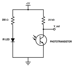
We do want to know where the carriage is on the knitting machine to allow us to accurately change the color of yarn at the correct time for the desired patterns to be created. To do this we plan to use a linear position encoder using an IR reflectance sensor and circuit. The circuit will be identical to the circuit used in Lab 3 and is shown on the right. We also are considering using a rotational encoder instead but will use the IR circuit initially. In addition, we will need to home the carriage in order to initialize the position tracking starting at the correct location. We will use a limit switch attached to the chassis to automate this process. We plan to have limit switches on both sides of the chassis to prevent runaway carriages while we are working out bugs on the code and testing side of the process. They will act as power cut off switches after homing.
The electrical system will need several motors. First and most important is a DC motor to move the threaded rod and by extension, the linear cam. If needed, we may upgrade to a stepper motor if the power is needed. We also need actuate color switching and needle activation/deactivation. Needle activation/deactivation occurs on both sides of the carriage independently. Thus the electrical system and powering needs to accommodate up to 4 motors.
We are most familiar with using Ardunio code for embedded systems. As such we will use an Arduino Uno as our microcontroller. If possible we will work exclusively off of the Arduino's power (5v, 3.3v, and GND). We end up needing more power for our motors we will additionally use an Adafruit Motor Shield and 12V power supply.
Finally, all good electrical systems have an emergency stop button which completely cuts power to the system in case of emergency.
Our Build:
- Position Tracking: Linear IR Reflectance Encoder
- Homing: Limit Switch on Both Sides (Changed to Single Stop)
- Microcontroller: Arduino Uno R3 (Changed to include Adafruit Motor Shield)
- Power: Ardunio Uno (5V, 3.3V, GND) via Computer USB connection (Changed to include 12V power supply)
- Motors: Single DC Motor + 1 to 3 Servo Motors (Changed to Single Battery Operated Gear Box)
- Emergency Stop: TBD (Changed to Toggle Switch to Cut Power to Motor)
Planned Software System:
Direction for Desktop Decisions
Our goals are simple: be able to change features of a scarf via a GUI on the computer and communicate those choices to the Arduino. We have had previous experience with serial communication to and from the Arduino Uno to both collect/display data and to send parameter changes to code in the Arduino with out recompiling.
Our previous experience with graphics programming has been framed around Python and use of the Pygame library. In terms of personal learning goals for this project, we want to expand our knowledge of graphical user interfaces and have chosen to us PyGTK to help us towards this goal. We will also look into libraries that can be used to communicate with the Arduino.
We have two important data features that need to be sent to the Arduino. First we need to set and send row length and number (aka width and length of the scarf). As these numbers must be positive integer values, we will use the integer data type to encode the size data. The second set of data we need to send is the pattern data. There will only be two color choices so a binary pattern is appropriate. In order to be conservative with our data size we will store the binary information in hexadecimal for to allow for multiple steps of the pattern to be encoded in a single byte. This can then be translated into the appropriate row and stitch location using the row width parameter.
We plan for the GUI to allow for the user to set the length and width parameters then manually create the pattern from a grid of toggle-able squares. Two colors will be changeable from a sidebar and will update the colors on the grid pattern to allow for the user to fully visualize their creation. Additionally the size parameters will be limited to ensure commands sent to our knitter does not exceed the maximum dimensions of our machine.
Our Build:
- Language: Python
- Graphics Library: PyGTK
- Serial Commodification Library: TBD
- Size Data: Two Integers
- Pattern Data: Stream of Hexadecimal
Chocolate Chip Embedded Coding
We decided to use an Arduino Uno as our microcontroller . As the controller, it will need to be programmed to handle several important tasks.
First, it must receive information over serial communication from the GUI. We already have code that receives byte information over the serial port, understands the end of a command (data set), translates the bytes into a string or integer, and places it in an appropriate variable. For this project we will need to expand this to translate byte information into an array of of hexadecimals.
Next, it must be able to use the encoder data and motor direction to determine the carriages position over the needle bed. This position data will then be used to command when the motor direction switches and when yarn changes occur. It is important that this switch is timed correctly to allow for the correct color to be used in the patterns.
Our Build:
- Language: Arduino
- Libraries: None (Changed to include Wire and Adafruit_MotorShield Libraries)
