Grandma's Favorite
  • What
    • Goals
    • System and Design
  • How
    • BOM
    • Sprint 1
    • Sprint 2
    • Sprint 3
    • Sprint 4
  • Who

Sprint 4

We're down to the final stretch.

Sprint Goal:
Finalize current system for MVP, and create the final iteration

Overview:
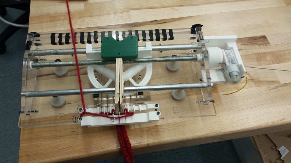
​​This sprint was about turning our research and experimentation into the final product, capable of simple knitting. In short, after lots of small, rapid iterations of each piece (to refine it from the nearly functional system last sprint), we have a polished automatic knitting machine. We got the mechanical system working with stitches forming with from the motion of the automated carriage with out human intervention. However the code and sensor attachment still needs work.

Pre-Sprint Events:
Several members of the team will be at the school during all or part of Thanksgiving Break. It is an opportune time to work on the project.


  • To prepare for the break, Claire designed a next iteration of the chassis to use for testing. The design was changed to allow for varied verge locations.
    • Aubrey laser printed the design out of 1/4" cast acrylic
  • Over the break itself Claire designed and 3D printed parts for improving carriage and improving the chassis build
    • To constrain the threaded rod in the side plates to allow for smooth rotation without causing stripping to the acrylic or threading, a bearing of a softer material than the acrylic and thread rod was needed. However bearings do not seem to come in the threaded variety. Instead bearings were printed with an inner diameter slightly smaller than the diameter of the rod. The bearings were then threaded using a screw of the same size and tpi as the rod. The grooves this created in the bearings allowed for it to be fitted on to the threaded rod. Several iterations were needed to get the sizing correct. Several feature were also necessary to add. First the bearings needed to have flat sides to allow for a wrench to be used to crank them onto the screw. Second the edges needed to be heavily filleted to allow for misalignment caused by imperfect threading.
    • Next to be added was a linear cam. Channel of the linear cam was made identically to the wooden iteration carriage with two adjustments: the needles moved farther out by  a centimeter,  and the angle of the cam was changed from 30 degrees from the line of the back to 40 degrees for mthe line of the back. The former change was made to allow for increased needle movement. The latter change was to prevent the cam from becoming to unwieldy with the increase in distance needed.
    • The carriage body was also created to support the cam as it moves over the needles.
    • As the last iteration needle bed had been made without a cover, one was made out of 3D printed PLA. The cover was designed to keep the needles form falling out of their  slots and increase the effective length of the slots by creating walls between slots. This keeps the needles form being able to move side to side when slide to to the farthest out position in the slot. As the print will be thicker than sheet aluminum do to the strength of the material, counter sinks were added to the holes to keep the screws from hitting the carriage as it passes over head.
    • The final piece added part to connect the motor and the thread rod more rigorously than the previously used hot glue method. The part is actually two pieces: a base and a lid. The base is designed to fit over the motor fitting and allow a servo screw to connect the motor to the printed part. The base also has a hole for a jam nut of the same size and tpi as the threaded rod. This nut is held in place by the lid The lid in turn is screwed into the base part and held there by two nuts which are coprocessed into the base.
Picture
Picture
Picture
Picture
Picture

Sprint Events:


Event: Construction
  • The team banded together to construct the testing platform

Event: Verge Tests headed by Aubrey and Claire
  • We used pieces of thin cardboard hot glued together to test the good locations for the two sided verge. We found the best location was farther out than anticipated and the chassis was cut to remove the front of the verge.

Event: Stitch Tests headed by Aubrey and Claire
  • Once the verge location was fixed we began testing stitch actuation--failure
  • We tried adjusting the weight on the weighted comb by adding more washers to it. This improved the cast off slightly but was not sufficient
  • We found that the yarn we were using , a colored cotton twine, tended to stick on itself
    • We switched to DK yarn and this improved cast off slightly
  • We tried waxing the yarn; no improvement
  • We tried increasing the distance between the needles by casting on only every other needle. This improved cast off slightly
  • We tried adding canola oil to the slots. This also improved the needle actuation slightly.
  • Finally, wondering if we would ever be able to get our project to work, we looked at OpenKnit. in the OpenKnit knitter we saw that teeth were used on the verge. Looking at other picture of knitters, we saw variations of the teeth were used on commercial models as well. We decided to give it a try.
    • The process for making the teeth was involve. We based our design off the OpenKnit teeth. We downloaded the STL file, converted it to a solidworks part, simplified the part and cut out all but one tooth and resaved the file as an STL. With a now simpler STL, we could create a linear array of the part to have any number of teeth we wanted. We additionally changed the base holdign the teeth to fit within the acrylic and added holes and overhanges by which we could attach the teeth to the chassis
    • It worked
    • We also printed out a removable front verge plate to allow for easier casting on while still keeping the constraint of having both sides of the verge.
  • There were still several bugs to be worked out: needles to tended to fall out of line with the cam after the carriage passed due to the weight of the comb and having no thread guide but our hands were among them.

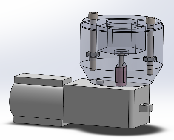
Event: Yarn Spool headed by Joe, Claire, and Aubrey
  • A spool and spool holder were created to hold the yarn and allow it to be pulled unwound by the knitting machine. The holder was wood, the spool was an empty 3D printer filament spool, and the axis was a tool steel round rod used in a previous iteration of our project.
  • Yarn was rolled onto empty 3D printer filament reel
  • Added ABS within the center hole of the reel to center the reel on its metal axle. This made the reel turn more smoothly, decreasing tension on the yarn

Event: More Acrylic  headed by Claire and Aubrey
  • After experimentation with correctly sized needles, it appeared that the space between the needles was too small. We created a needle bed for needles and gaps of 8.5 mm to be attached to the same place on the carriage
    • This, in concert with a new set of teeth, allowed us knit a complete row with almost no human intervention
  • We additionally cut out a new sleeker set of side plates which would better constrain the round rod axii and had attachments for a motor holder


Event: More 3D Printing  headed by Claire and Sean
  • Replaced boxy carriage with a  single 3D printed piece
    • Added attachment slot for IR sensor, and hole for the tensioning wire
    • Includes a slot for fishing line to pass through, to push the needles back into line just in case the weight of the scarf pulls them past the point where they could enter the cam to knit
  • Created motor holder to allow for the motor to be constrained at the correct location on the chassis and not need to be held in hand.

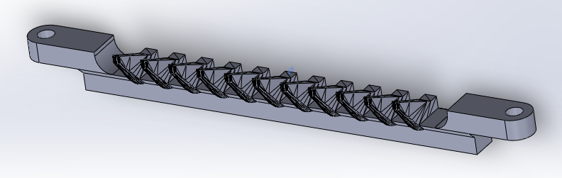
Event: Needle Guide  headed by Claire and Sean
  • Needles are pulled out of alignment with the cam slot by the weight of the comb and yarn tension after the carriage passed. The new carriage has a slot for fishing line, which is to be used ot guide the needles into the cam as it approaches.
    • The line was supposed to be flexible enough to bend with the cam as it went over the needles
    • We struggled to attach the fishing line to the chassis in a way that would both supply sufficient tension to hold the needles and that positioned the fishing line so that it was neither too high above the needles nor to low. The former caused the needles to slip out under the fishing line. The latter rubbed against the needle bed. 
    • We replaced the fishing line with thin stranded steel cable, and drilled holes in the chassis to let it through (it couldn't be anchored, because it wasn't flexible enough enough 
    • After a bit of tweaking this adequately constrained the needles and forced them to stay in line with the cam.

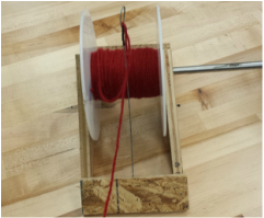
Event: Yarn Tension and Guide 
  • The thread needs to be at exactly the right spot to knit
  • We tried adding a tensioner to the spool but this caused too much tension.
  • We also tried a bent wire into a loop to hold it directly over the needles
  • The wire failed as it caused too much tension
  • We replaced the wire with paperclip guides, the lowest tension yet, which allowed the machine to knit without any outside help for the first time

Event: Circuit Holder headed by Paul and Claire
  • Paul CAD a circuit holder
  • Claire finished the CAD

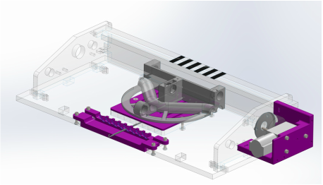
Event:  Test Integrated headed by Aubrey and Sean
  • The machine knits but the IR sensor gets caught on the tape and returns bad values. Additionally code does not account for carriage width.

Picture
Picture
Picture
Picture
Picture

Risks:
​Still no complete MVP!

Decision:
We decided to focus on completing and refining the small needle bed, and then expanding it until it was large enough to knit a human-wearable scarf, instead of trying to implement any new features. Additionally we would like our final iteration to be completely disassemble-able .  No hot glue or jankiness.
  • What
    • Goals
    • System and Design
  • How
    • BOM
    • Sprint 1
    • Sprint 2
    • Sprint 3
    • Sprint 4
  • Who