Grandma's Favorite
  • What
    • Goals
    • System and Design
  • How
    • BOM
    • Sprint 1
    • Sprint 2
    • Sprint 3
    • Sprint 4
  • Who

Sprint 2

Grab a cookie and settle in.

Sprint Goal:
Have an integrated product from GUI to needle motion.

Overview:
Project currently has carriage attached to chassis.  The carriage includes a linear cam and attachment for the IR sensor circuit board. However, the current attachment arrangement is wobbly. Sensor code and rig missing functionality. Needle bed attached to chassis but cam and needle followers currently jam. Desktop GUI for scarf size is currently integrated to allow for user input to determine scarf parameters on the embedded system. However, motor currently only moves in one direction due to IR sensor code not being the latest version. Yarn too think for needles

Sprint Events:

Event: Material and Design Meeting headed by Aubrey and Claire
  • Discussed design, materials, and integration for the needle bed, chassis and carriage
    • ​ Due to the cost of threaded rod, we decided to not order a new rod for our use. Instead we will use a more powerful DC motor in concert with a 12v power supply and motor shield to boost the speed of the rod rotation.  If needed, we can gear up the motor for increased speed.
    • We will use black ABS for all laser cut parts  except for those components that need to be light weight. Aubrey will acquire a thin material, preferably acrylic, for all components that need to be thin.

Task: Website Blog Framework to be moderated by Joe
HTML and CSS files exist in our Olin website folder. Blogs exist.
  • Website host switched to Weebly from Wix to allow access to HTML and CSS files
  • Aubrey, Claire, Sean, and Paul Have added post for sprint 1 and 2
  • Website files not moved to poe.olin hosting

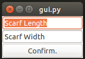
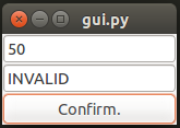
Task: 1-color GUI to be moderated by Sean
First iteration GUI. Allows users to define size of scarf. Limits users to integers and limits size to number of needles in needle bed.
  GUI sends two user-determined ints via serial ports.

  • Basic GUI made. After all it would just be silly if we could only make one specific scarf, over and over again. There are so many options! So, we needed an interface to be able to change things about the scarf.
    • It's just two text boxes and a button to print the output to the terminal, but it can easily be hooked up to the knitting machine, and control it that way.
    • It also checks the input conditions. If you enter 1000 for the width (much more than our machine could ever do), it won't allow it; it just replaces it with "INVALID" and refuses to print it to the terminal.
    • Size data set to the Arduino over the serial port

Task: 1-color Serial Receive to be moderated by Sean

Arduino code to receive GUI input over serial port. Data is moved into usable variable.  
  • During system integration serial receive code was added to firmware code modified from  Claire's serial read code from Lab 3 of coursework.

Task: Sensor Code Beatification be moderated by Paul

First iteration sensor code optimization attempt. Code commented. Motor directionality code included.
  • Paul made a first pass at commenting and simplifying his code
  • However, he did not push is code to GitHub by sprint integration and the code was rewritten by sean for testing purposed

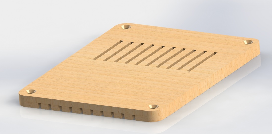
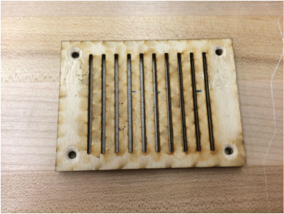
Task: Second Iteration Needle Bed to be moderated by Aubrey
10 needle acrylic bed. Horizontal needle positions consistent. Needles move smoothly within slots and allow for angled motion caused by cam. Attachable to chassis. Needles slide between 3 positions: stitch out, stitch in, and ignore.
  • To complete the dimensions the chassis and carriage, the size and hole location on the needle bed was needed. As the needle bed was late on being completed, Claire whipped up a quick model of the needles and the needle bed with the correct dimensions, including cam follower slot position and size, needle slots separation, and needle hook/follower/body sizes.
    • In order for the stitch to be correctly actuated, the needle needs to move passed the edge of the chassis (which is acting as the verge) far enough so that the loop (held at the verge) can pass completely over the open latch.  The needle also has to move far enough back passed the verge as to let off the stitch. We used a total distance of 2.5 cm: 2cm for the length of motion and 0.5 in leeway (the same size as the head of the needle).
    • The edge of the needle bed is set to be aligned with the verge to simplify measurements.  Additionally, countersink holes were added to the top to allow for the top of the bed to be flat when attached to the chassis. Slots were created with the distance of 6.5cm between the centers of the slot as is standard for mid-gauge machines.
    • The size of the needle bed materials was changed from the black ABS (0.25") that was agreed upon to a thinner wood (0.125"). This change was made due to the fact that the use of the thicker material would have completely covered the cam followers and thus would be unusable.
    • Holes for bed attachment to the chassis and the location of the axii holes on the side supports were adjusted on the chassis design to correct for the location and size of the mock needle bed.
  • Aubrey also made and laser cut a version later. It worked very smoothly but the channels were not quite long enough to allow for the deactivated needle position.

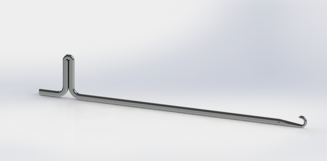
Task: Linear Cam Carriage to be moderated by Claire

Carriage with 10-needle linear cam. Attachments for sensor circuit and chassis.
  • ​Design considerations:
    • The linear actuation of the carriage is of an appropriate speed. Additionally the motor should not have to be held in hand.
    • The linear cam is placed and sized correctly for needle actuation.
    • ​​The entire build could be assembled and dissembled to allow for parts to be swapped out. This would allow for us to make changes to individual pieces as needed instead of completely remaking the chassis and carriage every time we want to make a change.
    • In order for the stitch to be correctly actuated, the needle needs to move passed the edge of the chassis (which is acting as the verge) far enough so that the loop (held at the verge) can pass completely over the open latch.  The needle also has to move far enough back passed the verge as to let off the stitch. Currently it is set to 0.5 cm but the decision was arbitrary.
    • The angle of the linear cam is 25 degrees compared to the back edge. This is less than the 30 degree maximum that modified sprint 1 needle bed allowed. As it was agreed that the second iteration bed would have equal or better response, this angle should be acceptable.
    • The carriage CAD is depicted to the right without its top to show the linear cam and the internal support braces. As there is no room below the carriage due to its closeness to the needle bed, we have implemented the use of braces and countersunk screws.  Other designs involving the carriage components interlocking to keep them together cause parts to hang below the base of the carriage. Attachment method for sensor circuit board also shown.
    • There is no screws attaching the top plate to the carriage. Instead only the tab and slot method is used to hold it on. This is to allow for the top to be removed for needle motion observation and for easy access into the carriage and carriage top plate for modification of attachments such as the yarn tensioner and the thread color changer.
    • Axii holes were arbitrarily placed with the constraint of maximizing space within the carriage for carriage attachments. CAD models for said attachments have not been completed in time for inclusion in the laser cut model and the design is such as to accommodate them being added on last minute.
    • The first iteration of the chassis and carriage involved the use of two axii, one support rod and one threaded rod. This iteration changes the a three rod system. This decision was made to allow for the thread rod to be as non-load bearing as possible. This lowers the torque needed to actuate the carriage. As such more of the motors power can be used or gear towards speed.

Task: Acrylic Chassis to be moderated by Claire
Acrylic chassis with appropriate attachments for carriage, sensor strip, and motor 

  • ​The chassis is composed of four main pieces: the base, the two side supports, and the back. These pieces are fitted together using tabs and slots and held firmly in place with #4-40 screws and nuts. The thickness of the pieces (0.25") is essential to allow the screws to attach the components together.  The nuts have their own slots within the plastic to hold them, and in turn the screws, in place. We plan to use narrow 4-40 nuts to allow them to sit completely within the base and side supports. This will allow the base to sit flat against the table. Because of the chosen attachment methods, the chassis is completely able to come about and have pieces swapped out.
  • In addition to the main components, there is an additional sensor bar. The sensor bar sits about 3mm below the IR reflectance sensor when the carriage is suspended on the axii rods. This is within the 0.2-12mm range of the sensor and is preferable to a farther distance to to the increased response of the circuit at close distances. An increased response equates to a cleaner cut off threshold for determining color and thus position.  The sensor bar rest on top of the back support and is held in place by sliding into slots in the side support. Aligned slots in the bar cause the bar to be constrained in the direction parallel the axii rods.  This leave the bar able to be removed and swapped out but leaves it constrained when slid in place on the chassis.
  • Updated chassis and carriage CAD:
    • Once the real needle bed CAD file was completed, the chassis and carriage CAD could be updated. Unfortunately the length of the slots was longer than the length needed to actuate a stitch but shorter than need to allow for needles to be placed in the off position.
    • Carriage top shown as semi-transparent.
  • Motor attachment not implemented in CAD
  • ​​The original design required holes to be drilled in the sides of the acrylic.  Unfortunately the drill press could not be lowered sufficiently far to allow for the sheet to drilled along the long direction. We tried to use a Dremel tool and desk clamp, however the rotary tool did not have enough torque to drill into the sheet. Additionally the plate for the motor and Ardunio on the base plate got in the way of the Dremel. Instead the side supports were hot glued to the base. This make the side plate unable to be removed and exchanged. The screw and nut attachment was able to be used for the base plate and side plates. The precision of the screw holes that were drilled through the side of the acrylic was not high and this method of attachment should not be used as is for the next iteration.
  • Countersink chamfers were added by hand using a file. A round engraving was added in the bottom of the base plate to house the nuts for the needle bed attachment. This way the chassis would lay flat on the table.  A paper sensor sheet was glued to the sensor bar. Stripes wear made such that white and black strip each represent a needle.

Event: Needles Arrive headed by Claire
  • ​Needles arrived today.  They have been verified as the correct dimensions for the MK70 HK160 Needles For Knitting Machine Singer/Silver
  • Quantity: exactly 50
Picture
Picture
Picture
Picture
Picture
Picture
Picture
Picture
Picture
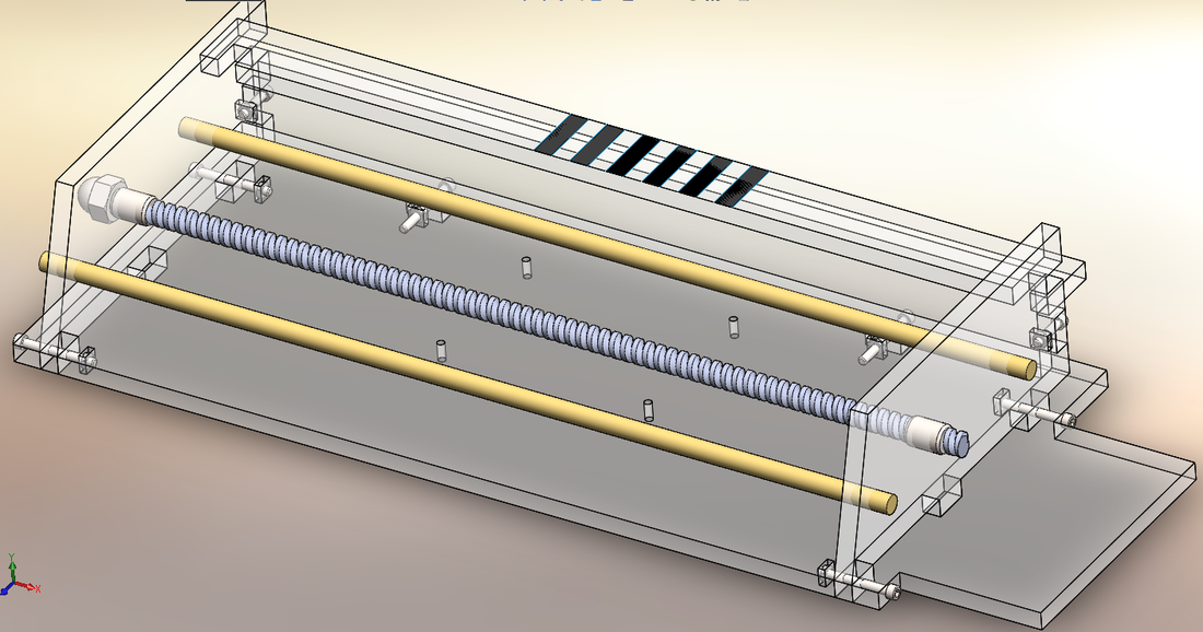
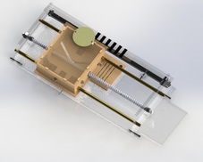
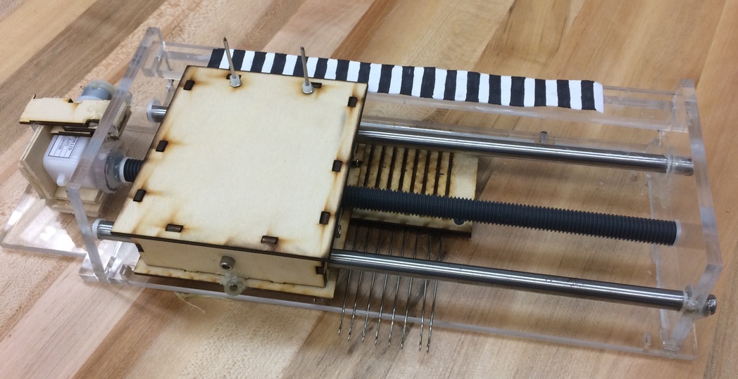
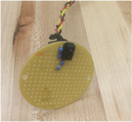
Picture shown is from after system integration. Neither the motor nor the washer thread guide existed initially.
Picture
Picture
Picture
Picture
Picture
Task: 2-color GUI to be moderated by Sean
GUI allows pattern to be choose from clicking a grid. Grid slots can be selected or deselected.  Allows users to define size of scarf. Limits users to integers and limits size to number of needles in needle bed. GUI sends user determined size and .pattern information over serial port.
  • Starts as a blank sheet, but you can draw on it to make patterns for the scarf (like a squid, for example (to the right)).
  • Currently the implementation of the GUI is partially limited to the physical build being able to support two-color pattern.
  • Translation of data into hex and transmission to Arduino not implemented
  • Scarf size definition not implemented

Task: Formal Sensor Rig to be moderated by Paul
Sensor circuit rig to track carriage position over needles on solder prototyping board. Has female pin headers for output/input/ground wires.  Uses Arduino to track needle position. 
  • Sensor circuit moved form breadboard to soldered round protyping board. Lead wires attached and heat shrink tubing used to electrically insulate bare wire that could touch.
  • Female header pins not used at suggestion of instructor

Carriage Motor Code to be moderated by Claire

Carriage moves back and forth across needle bed the number of times determined by size variable. Motor direction stored as variable for use by needle counter.
  • Claire made a first pass at this code, but with the IR sensor code not up-to-date on GitHub, the confusion on why such simple code did not work was much
  • Sean also simultaneously made a version of this code, not realizing the task had been assigned to Claire. Again the sensor code through off the function.

Task: Website Pages to be moderated by Joe
Additional pages exist on website: who/about us, what/project description; recipes.  HTML and CSS files exist in our Olin website folder. Relevant pages exist (can be empty).
  • Claire added two new pages  to our site
    • Firstly, we now have a formatted about us page labeled in the tab bar as WHO. The formatting is based off one of Weebly's preset templates (I believe in the portfolio section) and then expanded to accommodate all 5 members of our team. The page begins with a quick descriptions of our team on whole and the context of Olin. The page then precedes to give each member a section of one main photo, two minor photos, a small section of descriptive text, and an option to link to their personal sites.  Members are listed alphabetically by first name.
    • Secondly, a new bill of material (BOM) page has been added. Materials are separated by sprint and subsystem iteration. eventually we will add a link to a formal BOM that shows a listing of all materials used without repeat as well as actual and estimated costs and cost of the final iteration.
  • Project description and grandma's cookie recipes pages not added
  • Pages do not exist on poe.olin host

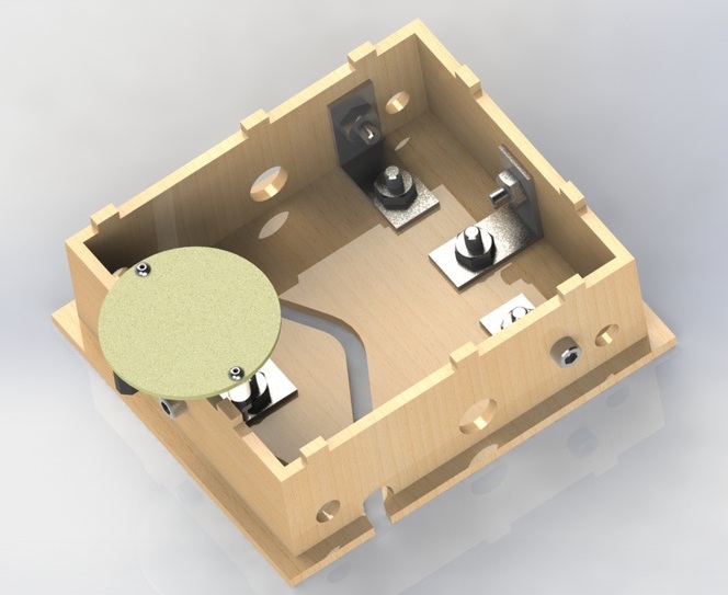
Task: Color Change to be moderated by Aubrey
First iteration yarn color changing rig. Assumed eventual attachment to carriage.
  • Some research started; no implementation

Task: Yarn Tensioner to be moderated by Paul
First iteration yarn tensioner. Focus on tensioner placement to land over open needles and adjustability on applied tension on string.  String should be held over needles. 
  • Some research started; no implementation

Task: 2-color Pattern Serial Receive be moderated by Sean
Arduino code to receive GUI input over serial port. Data is moved into usable variable. 
  • Not implemented

Task: MS Paint App to be moderated by Sean
GUI allows for color selection of yarn. Limits users to two colors. Visualize pattern with chosen colors.
  • Not implemented

Task: Motor Homing to be moderated by Paul
At start up, Arduino homes to the right side. Uses Arduino and mechanical motor stops. Requires mechanical stops to be acquired. 
  • Not implemented

Event: Chassis and Needle Bed Integration headed by Claire and Aubrey


  • We attached the needle bed and needles to the chassis
  • When rotated by hand, the threaded rod moves the carriage over the needles. The needles don't easily stay inline with the linear cam when outside it, and when the needles are within, the carriage and needle occasionally jam.  By removing the top of the carriage, the interaction of the needles and cam can be examined. It appears that several problems are compounding. First, the needles are not held upright in the slots. Second, the cam is loose enough to wiggle atop the needles when they fall diagonally in their slots. Third the front of the needles are unconstrained cause them to turn slightly within their slots. Finally, the allowance off the axii holes allow for the cam to move up and down slightly. Wiggling the needles fixes the jams, but when the machine is automated, this solution will not work
  • Glues a washer to the base of the carriage and used it as a yarn guide.
    • it worked acceptably well
    • however the yarn was too thick for the needles and kept coming off or being split by the hook
    • We plan to downgrade to a thinner yarn in the next iteration as well as adding a weighted comb to attach to the knit fabric to help keep the thread loops down and on the needles during knitting

Event: Full System Integration headed by Sean and Claire
 
  • Initially we focused on trying to not have the needles jam when the carriage passed over but realized we needed to make major changes to fix the problem.
  • Next we checked to see if the motor system worked. We attached the motor to the thread rod with hot glue and created a plywood motor holder out of scrap wood and glue. We found that the janky attachment method of the side plate to the base plate allowed the front of the side plate to move upward when the motor rotated. This did not seem to negatively affect the cam actuation so we left it as it was. 
    • Motor Specs:
    • ​​Name: Vigor Precision BO-1 Gearbox
    • Operating Voltage: 3.0-12V
    • Max Unloaded Speed: 180 rev/sec
    • Max Torque: 0.8-5 Kgf*cm
  • Next we checked the code. At first we thought that the jamming of the needles and wiggling of the side plates was through off the sensor but after a little manual experimentation with the sensor, we realized we did not have the most recent (aka working) version of the sensor code.
  • To the right shows the system working (sans correct sensor data) up until the needles jam -->
Picture
Picture
"Bologna and orange marmalade? In my day, we just ate PB&Js."  ~Grandma
"Oh no! Mr. Fluffles got in my yarn basket again. That silly cat." ~Grandma

Risks:
Currently the needle bed and cam do not play nicely together. The cam line is not held stable and the needles turn within their slots. This, in combination with the friction of the cam material causes the cam to jam mid-row.  If we don’t fix the cam/needle relationship, we will be unable to make our minimum viable product. To mitigate this risk, we will focus our entire next sprint on needle/cam actuation. We plan to have each member of the team make multiple changes and iterations of the two parts in order to resolve the issue.

Decision:
We have decided to focus on a stable, simple system over the original many features approach in order to ensure basic functionality. If we do manage to get basic functionality working, we will additionally work to create a color changing system. We have completely dropped the idea of using purl stitches due to the complexity of the mechanical system needed to make this possible. We plan to approach this by making as many iterations as possible as quickly as possible to find a solution to the cam/needle mismatch. We additionally found that the needles are of a size they split worsted yarn. To resolve this, we plan to use light worsted or fingering yarn weights.

Next Sprint:

Goal: Automatically produce a small multiple row knit test piece
  • We assume that once the issue of cam/needle partnership is resolved, creating a small sample piece will be trivial.

For the coming sprint we plan to:
  1. Update the needle bed to have correctly sized slots to allow needles to be placed in the off position,
  2. Update the needle bed to keep needles upright in slots,
  3. Rigorously attach the motor to the chassis,
  4. Bridge the linear cam slot to increase its stability,
  5. Lower the friction between linear cam and needles by adding slicker materials,
  6. Lower the friction between linear cam and needles by adding rollers to the needles’ cam followers,
  7. Add a needle guide to aid needles moving into the cam correctly,
  8. Add counting and rigor to the sensor rig and code, and
  9. Add accessories such as yarn guides and the yarn comb to allow for the small sample piece to be made.

  • What
    • Goals
    • System and Design
  • How
    • BOM
    • Sprint 1
    • Sprint 2
    • Sprint 3
    • Sprint 4
  • Who