Grandma's Favorite
  • What
    • Goals
    • System and Design
  • How
    • BOM
    • Sprint 1
    • Sprint 2
    • Sprint 3
    • Sprint 4
  • Who

Sprint 1

We're just getting started.

Sprint Goal:
Initial attempt will be made on all project components.
(
Project components: Needle Bed, Chassis, Carriage, Motor Control, Location Detection, Desktop GUI, and Website)

Overview:
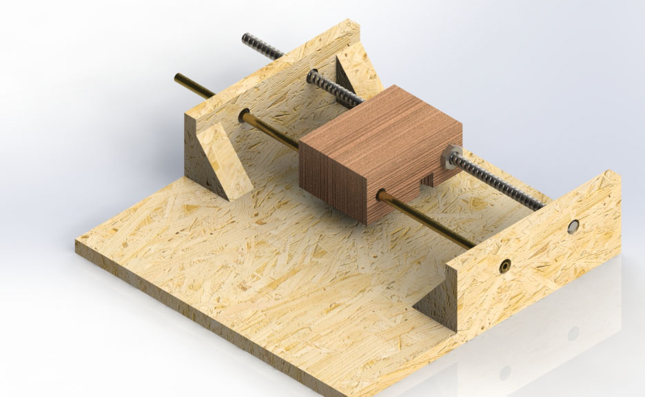
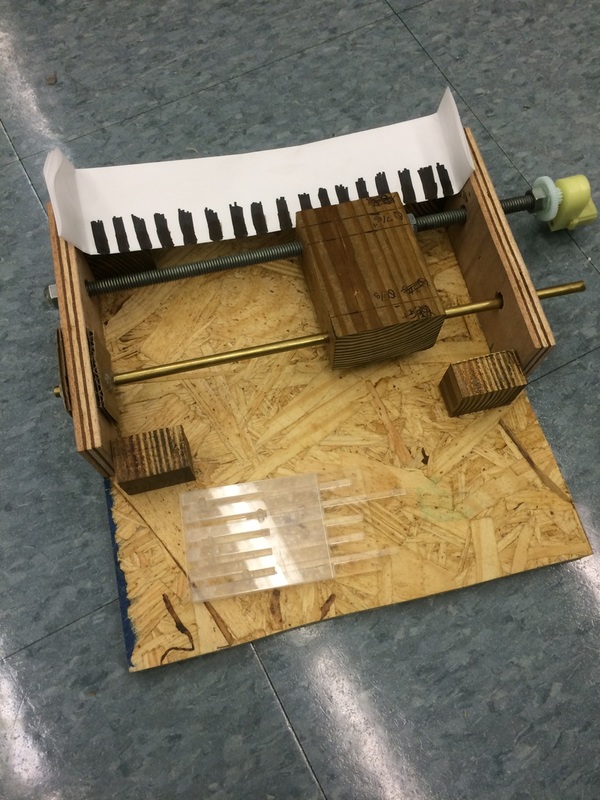
First iterations of chassis, carriage, and position sensor created and integrated. Motor unconstrained and must be held by hand. Speed of carriage very slow. First iteration needle bed created but not integrated. Work on GUI code begun but not functioning/integrated.  Framework of website created in WIX.  Next time we will focus on total project integration.


Sprint Events:

Task: Order Latch Needles to be moderated by Claire
  • ​Needles for the MK70, a mid-gauge Singer knitting machine have been purchased!
    • They should arrive square in the middle of Sprint 2.
    • Picture include in drive for needle bed and carriage dimensioning

Event: Linear Cam Sketch Model headed by Sean
  • In order to increase understanding of the basic mechanics of knitting machines for himself and others on the team , Sean spontaneously decided to throw together a quick model of the carriage and needle bed out of cardboard.
    • ​The basic principle of a knitting machine is that the individual needles are constrained to slide back and forth within individual channels- this simple back and forth motion is enough to reach out and grab yarn, then hook it through the last loop that was made. Each needle has a cam follower, which is just a protrusion that sticks out above the flat surface of the needle bed so that it can engage with the carriage as the carriage is slid across. A channel in the carriage is angled so as to push each cam follower forward and then back as the carriage moves.
    • In our cardboard model, we cut out five mock needles and put them in channels between two sandwiched cardboard sheets to form the needle bed. The carriage was a separate piece of cardboard with two strips glued perpendicular to its surface to form the channel. Although Claire and Aubrey were already working on more official carriage and needle bed prototypes, the simple cardboard model helped the group better understand what was being discussed. And we were excited to bring it into class to prove to the instructors that we hadn’t chosen too difficult of a project- after all, it can’t be that hard if we can make it out of cardboard! Right?
      • ​Ha.​
Task: First Iteration Needle Bed to be moderated by Aubrey
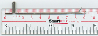
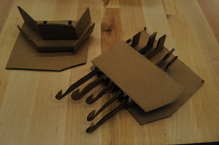
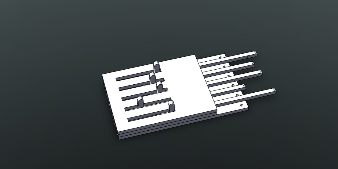
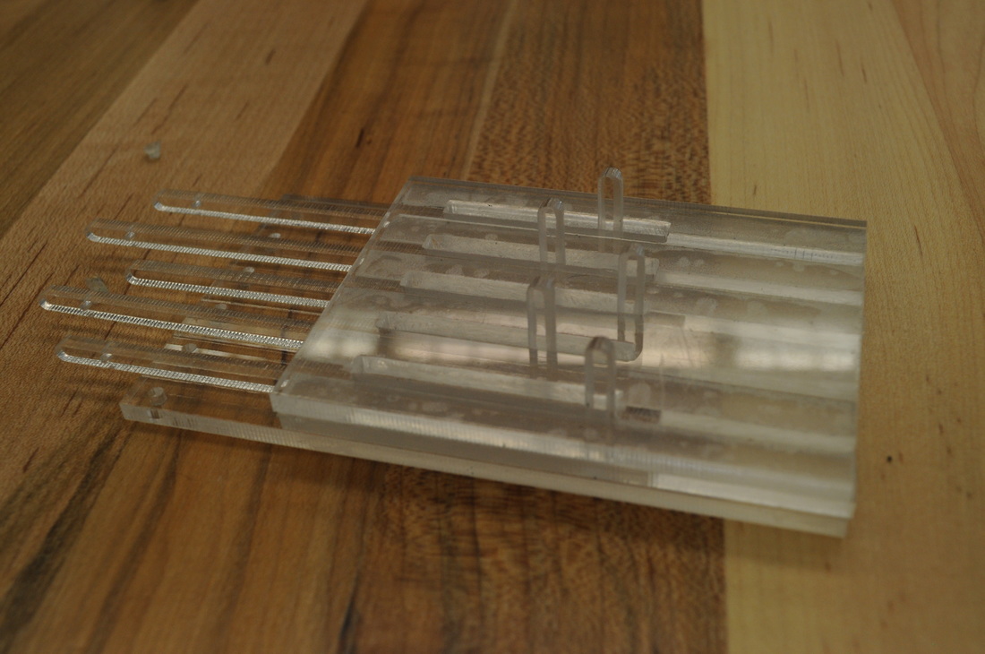
(First iteration of needle bed sized for 5 mock needles. Should include mock needles with cam followers. Laser cut from acrylic. Needles are held individually such that the cam followers are upright. Needles can glide smoothly on bed.)
  • New laser-cut prototype for the needle bed!
    • Aubrey spent a few hours over the weekend making a virtual needle bed of five needles in SolidWorks and then she laser cut it out of an 1/8" thick cast acrylic sheet we found in the MechE stockroom.
    • ​​Because we were limited to using the thickness of the sheet as one of the dimensions for the pieces, this needle bed was still just as simple as the cardboard version (needles in channels sandwiched between two flat sheets and held together with double-sided tape) but with less friction and more precision. Though Aubrey did her best to keep the dimensions of the acrylic needles consistent with those of the needles we’d ordered, there was no way to make them as thin as the actual needles would be, so we’re going to have to remake the test needle bed once the actual needles arrive.
    • While the acrylic needles did slide much better than the cardboard ones, we noticed after assembling the laser cut needle bed that whenever the needles were pushed to the side of their individual channels they would no longer slide at all. Because the carriage has to apply force sideways across the needle bed by design, this wasn’t a problem we could ignore.
    • ​We identified two potential causes for the problem:
      • Laser cutting had left ridges in the sides of the needle channels that might be adding unwanted friction.
      • The acrylic cam followers on the needles were very square and therefore probably not the best at distributing force.
    • The solution to both issues? Lots of sanding… but would it destroy the shiny, clear perfection of our freshly cut acrylic?
    • Once Aubrey had filed down all the needle channels and cam followers, the needles did slide a lot better in their channels and tended to catch much less when pushed from the side.
    • There was still a limit to the ratio of lateral to forward/backward force: we couldn’t make the angle of the stationary cam too steep or the needles wouldn’t move. Aubrey used the "very scientific" method of pushing Sean’s comb against the needles at various angles until they began to stick, then recorded what the maximum angle (30 degrees) was so that Claire could use it to inform her design for the next iteration of the carriage.
    • She then tried her best to get the acrylic dust off her hands… and hair… and laptop… and literally everything else.

Tasks: First Iteration Chassis and Mock Cam to be moderated by Claire
First iteration of carriage and chassis. Mock carriage with linear cam to cause motion of mock needles. Hook up motor rig for linear motion to Arduino.

  • Design is based on a 5-needle needle bed. As this was to be a quick model, materials were based on found materials such as fiberboard and scrap wood. The axii diameters are based on scrap rods and thread rods.
    • The carriage is held high enough off the chassis to allow for the needle bed to be beneath and the needle follows to be within the cam.
    • The rods are held apart far enough to allow for the existence of a linear cam to be router-ed between them. The cam size and shape is currently arbitrary. To to lack of router training the channel was instead partially created using a Dremel tool.
    •  As the thread rod is rotated, a nut attached to the cam is forced along the threads of rod. This moves the  carriage linearly across the rods.
    • ​The chassis was made to be large enough to allow for the carriage to pass over every needle be of the bed completely without hitting the walls of the chassis.
  • The wooden component shapes were created using a band saw and drill press.
  • As the needle bed did not allow for proper cam/follower behavior (this was post sanding), no integration was attempted between the cam and needle followers.
  • A large tolerance was given on holes for the axii to allow easy motion even under poor hole alignment. The axii, one brass hollow rod and one threaded rod, were also scrap material and thus not set to particular specifications other than minimum length.  Wooden pieces, rod, and motor were attached via hot glue for speed of construction.
  • The DC motor was chosen such that the power needed could be supplied by the Ardunio. It is not constrained to the chassis and thus must be held in hand when on in order for the rod to turn instead of the motor.  The motor is powered directly from the voltage and ground ports of the Arduino. Motor Spec:
    • ​​Name: Vigor Precision BO-3Gearbox
    • Operating Voltage: 3.0-4.5V
    • Max Unloaded Speed: 120 rev/sec
    • Max Torque: 0.4-1 Kgf*cm
  • We found that the turns the rod very slowly. We will need to use a more powerful motor in the next iteration.

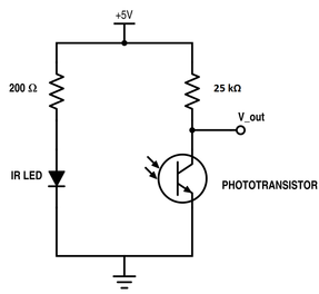
Task: First Iteration Sensor Rig to be moderated by Paul 

 First iteration sensor rig to track carriage position over needles. Arduino should output correct number of needles passed to serial monitor when motion is in one if not both directions.
  • For the electrical component of the project, we created a circuit using an IR sensor that returned a signal that could be processed by the Arduino.
    • The IR sensor changes voltage output based on the light that it reflected from nearby surfaces. In order to stay in a linear range of voltage changes we needed to use the proper resistors. We used Kirchhoff's Voltage Law and the IR Refelcectance Sensor Spec Sheet to find the correct resistor to use. The estimate was about an order of magnitude off from what we actually needed as was to be expected do to difference in surface reflectivity. Power, ground, and v-out connect to the Arduino.
    • With the IR circuit we used printer paper and black sharpie to each corispond to a single needle.  Every time the carriage goes over a strip boundary, the voltage changes considerably. We programmed an Arduino show the voltage output in the serial monitor.
  • Needle counting not yet implemented

Task: Website Framework to be moderated by Joe
Blog-style website framework allows for post/updates page, project description page, team page, etc; Adding embedded images, videos, etc should be worked out. Should be ready for other members to start adding project info to update page. First draft of project information ready for peer review.
  • Blog-style website has been implemented in WIX. First post created
  • First draft of project description not created

Task: 1-color GUI to be moderated by Sean

First iteration GUI. Allows users to define size of scarf. Limits users to integers and limits size to number of needles in needle bed. GUI sends two user-determined ints via serial ports.
  • Research of PyGTK begun

Event:  Sensor and Carriage Integration headed by Paul and Claire
  • We attached the breadboard and circuit to the wooden carriage with double sided tape. The Arduino rested atop top the breadboard. Additionally we added a strip of paper with black sharpie lines was added to the chassis. The system in its full, slow glory is shown in the video to the right -->
    • We found that the tape was an insufficient means of holding the Arduino and bread board. However the circuit components stayed in place on the top of the carriage well enough to check functionality of the integration as long as the carriage and chassis were not bumped. 
  • We noticed that the IR circuit was returning odd, random-ish numbers
    • To help debug the issue we set a cutoff threshold for the values. Values less then the threshold (black lines) displayed as zero in the serial monitor, and values greater than the threshold (white) displayed as one in the serial monitor.
    • Instead of getting a set of ones then a set of zeros and so forth, ones and zeros were jumbled together and the borders between the two colors.  To fix this and output to the serial monitor simpler, we added debouncing code. This caused the circuit to only trigger a change in displayed number if the circuit had sensed that color without variation for a certain amount of time (20ms).
    • Additionally the code limited the display to only show when changes to the number occurred instead of once every loop of the code. This behavior is shown to the right -->
    • With another couple lines of code we should be able to count the number of times the sensor crosses needles, giving us an accurate location. 
"How old are you now? Ten? Eleven?" ~ Grandma
Picture
“And it won’t move? It’s all this technology you’ve tried to use. What you need is a good, quality woodsmith.” ~ Grandma
Picture
Picture
Picture
“Young people these days are far too impatient.” ~ Grandma
“Don’t forget to wash behind your ears” ~ Grandma
"A carriage? Where is the horse? How does one get anywhere in that strange contraption" ~Grandma
Picture
Picture
"Now that's a pace I can understand. Normally you young folks are in a rush to to everything." ~Grandma
Picture
"What are you typing? That looks like gibberish." ~ Grandma

Previous Goals:
We desire to have a knitting machine with multiple feature capabilities such as multiple stitch types (purling and knitting), multiple colors patterns in a single garment, and possibly lace-patterning. The trade-off is a less polished final product with possible jankiness used to hold the machine together and allow for the expanded functionality.  Our individual learning goals include learning about graphic user interface (GUI) creation, practice in machining, and improving our knowledge about mechanical joints and linkages.

Risks:
We assumed that the known mechanical system of a linear cam carriage and needle bed with cam follower needles will work as described. However, the needles in needle bed oppose motion that is not parallel to the slots. If our rendition of the system doesn’t work as expected we have no backup plan for creating the system. To mitigate this risk, we will focus on getting our system integrated completely in order to test the system and make any corrections that are necessary.

Decision:
We have decided to focus on integration and stability in order to ensure basic functionality. This likely means each iteration will be more formally made to ensure parts fit together.

Next Sprint:

Goal
: Integrated product from GUI to needle motion within bed.
  • With this level of integration and functionality, we should be able to focus on stitch actuation for sprint 3.

Improvements for the coming sprint:
  1. Update the needle bed to accommodate the size of the real knitting machine needles which are thinner than our acrylic sheet mock needles,
  2. Update the needle bed to allow for needles to be in an off position, aka not get caught by the carriage so that scarves can be of varying widths without half stitches being formed,
  3. Purchase a threaded rod with greater distance between threads to allow for faster motion of the carriage,
  4. Attach the motor to the chassis such that we do not have to manually hold the motor to allow for motion,
  5. Add counting and an attachment method to the sensor rig and code, and
  6. Make GUI data available to the Arduino
  • What
    • Goals
    • System and Design
  • How
    • BOM
    • Sprint 1
    • Sprint 2
    • Sprint 3
    • Sprint 4
  • Who