Inkscape
Sprint Three
The stories of Dixie and Edna
Chartreuse, Leveling up: Dixie
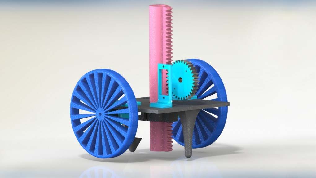
 Dixie (shown above) was our first full mechanical integration! We were able to integrate a pen actuator with a rack and pinion, in order to be able to move the pen up and down to lift and lower the pen, thus allowing more freedom in drawing. We also designed custom-designed wheels that are smaller to continue with miniaturizing the project and (why?) and were able to create a symmetric chassis. We also created structure for electrical integration by creating a mount for the Arduino board.
Enter Edna
 When we built Edna (CAD render shown above), we gave her larger wheels with rubber traction for better grip on the ground and an asymmetric chassis.
 Edna was our first iteration where we did not utilize the Arduino. We finalized the PCB design (shown to the left), integrating all the necessary elements (motor shield, WiFi chip, etc). However, due to time constraints, by the time we were finished designing the PCB, it was too late to order it for the PCB to arrive in time, so we pivoted to recreating the circuit on a protoboard (shown on the right).
  We began with a protoboard and an ATMEGA238 chip, which acted much like the Arduino. However, we ran into issues with uploading code to the ATMEGA238 because the crystal oscillator used on the protoboard ran on a different clock and thus it was difficult to sync up the ATMEGA and the protoboard. Another design decision we made was to use the ESP8266 WiFi chip. We could've alternatively used a WiFi shield on an Arduino, but this would consume physical space to mount it and program memory space to run the WiFi connection code on the Arduino (and we were already strapped for memory space). The ESP was much smaller physically and had its own processor that could facilitate WiFi connection, thus it was a better choice for us.
Our main focus with Edna’s software was implementing a feedback loop to control her motion effectively. We started by (successfully) implementing encoder position control on the Arduino, which gave us the ability to move the robot specific distances. We then successfully implemented encoder translation, creating a translator/decoder ROS nodes so that the computer and the robot would know both where it was in space, and where it was supposed to be going. In conjunction with the decoder and encoder nodes, we adjusted our path planning algorithm to complete the encoder position control loop efficiently. We did so by making the following changes: