Inkscape
Sprint Two
The story of Chartreuse
Mechanical Design
 Using the same design as Bertha, the chassis for Chartreuse (shown on the left) was edited in minor ways. The main goal for the mechanical structure during this sprint was miniaturization. Starting with Bertha’s chassis, we were able to move fixtures and remove unused space to create Chartreuse’s smaller chassis. During this process, Chartreuse actually went through two chassis versions, the first featuring a slight mistake in the placement of the Arduino mounting holes, which was fixed in the second (and final) chassis for Chartreuse.
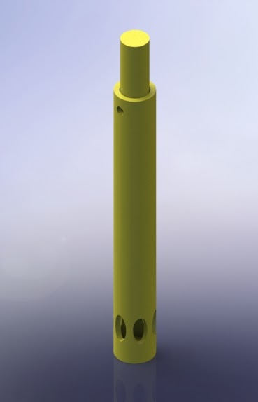 While Chartreuse never had an implemented pen holder, we had, at the same time, created a new, redesigned pen holder (shown on the right) that had a smaller footprint and would allow us to more easily include actuation in the future. This pen holder was essentially a tube that would hold the Sharpie in place (allowing the tip to stick out the bottom) with a spring and fixed stopper in the top to hold everything in. The pen holder was intended to be attached near the center of the chassis instead of hanging off the end. As a nod to her name, Chartreuse was 3D printed with light green filament.
Software Design
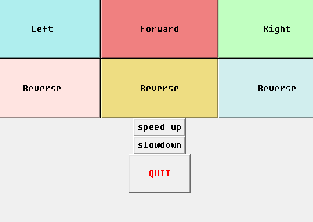 We created a simple, responsive graphical user interface (GUI) (shown on the left) in Python using tkinter to respond to user input in a more elegant and accessible way than simply typing commands into the Serial monitor. The user can interact with the GUI by hovering over or clicking the buttons to cause the robot to change its motion appropriately. Each button on the GUI has a unique function attached to it, which sends the appropriate message to the Arduino through the Serial port (using pyserial). We reused the message processing code we implemented for Agnes and Bertha in order to make Chartreuse respond to the received message.
 We also began to investigate/prototype autonomous motion by starting to develop a path-planning algorithm. Our first iteration of a path planner uses the Canny edge detection algorithm to identify edges in an image, and then converts these identified edges to vectors (with respect to our defined origin, the bottom left corner of the canvas) that the robot can drive along (illustrated on the right). We also updated the controller for the robot to use differential drive, to make it easier to drive the robot along a specific vector and thus integrate with the path planner.
 Further along the lines of integration, we began to set up a basic system architecture (shown above) for our system using ROS, which is displayed in the diagram above. We set up our basic system architecture to allow us to easily add multiple robots if we wanted to/had the time to, and to use ROSSerial (which communicates to the /serial_comms topic) as the communication hub.
As part of beginning to set up the basic system architecture, we also started to experiment with ROSSerial to communicate with the ESP8266 WiFi chip. Ultimately, we were unable to get ROSSerial working because it was too bulky for our Arduino Uno. The Uno can only handle running either one publisher or one subscriber at a time before running out of program memory space; the communications protocol with only one subscriber took up 86% of the space on the Uno, which clearly indicated that the Uno wouldn't be able to support our vision.
We considered pivoting to using an Arduino Mega, which has more memory and thus could better support our system. However, we realized that implementing a TCP/IP socket protocol via the ESP8266 WiFi library instead of ROSSerial would take up only 17% of the memory space on an Uno and 22% of the memory space on a Nano, and we really wanted to tend towards smaller microcontrollers. Therefore, we decided to pivot to using a TCP/IP protocol with an Arduino Uno, rather than putting ROSSerial on a Mega.
We acknowledged, however, that a raw TCP/IP protocol only does the bar minimum to prevent data loss, whereas ROSSerial has built in infrastructure to ensure good message flow. We mitigated this risk by implementing standard message checking by checking to see if we recieved both a start message marker and end message marker and checking for the confirmation flag indicating that all the important information had been successfully transmitted. We also acknowledged that the TCP/IP connection would be slow (communicating at a rate of 2Hz), but we prioritized quality of the output created by our robot over the speed, so we thought this was an acceptable drawback.
Electrical Design
 One of the major developments we made with Chartreuse was starting to shift away from using an Arduino. We started our project using the Arduino because of its familiar and easy layout and integrated motor shield. However, we wanted to repackage the elements of the Arduino and design a different electrical system because the Arduino didn't support wireless communication and was also very bulky, which didn't work well with our goal of miniaturization. Many members of our team also really wanted to learn PCB design as a crucial part of their learning experience for the project. As a result, while building Chartreuse, we also began experimenting with what the next iteration of our electrical system would look like. We started by decomposing an Arduino Uno and building it on a broadboard as a experiment (shown above). Our main focus in this experiment was being able to program on an ATMEGA 238 using an FTDI chip (which would capture the essential elements of the Arduino). By deconstructing the Arduino and replicating it on the Arduno, we were able to gain a better understanding of the internal circuitry of the Arduino, which helped us when we were designing our PCB.