Inkscape
Do It Yourself Guide
An extensive guide to creating your own version of Inkscape.
System Overview
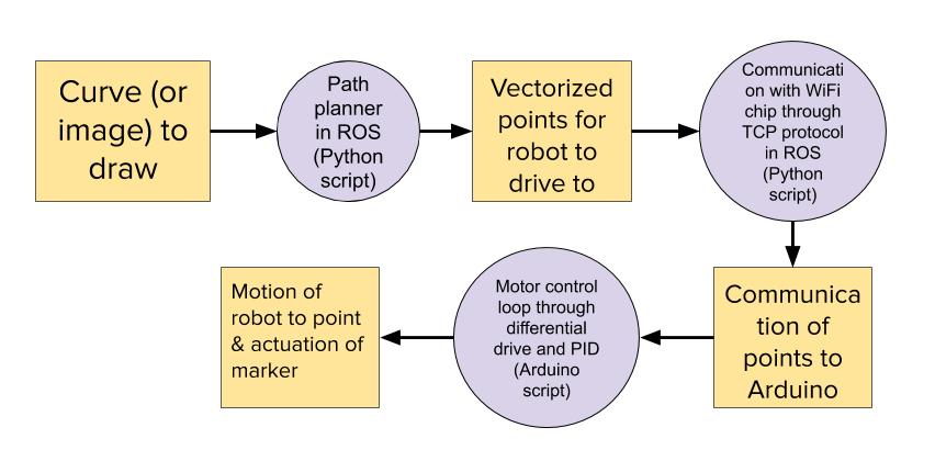
The image above shows the underlying processes that work together to make Inkscape work. In the following sections, we'll explain how each subsystem works in order to complete each of these processes.
Software Subsystem
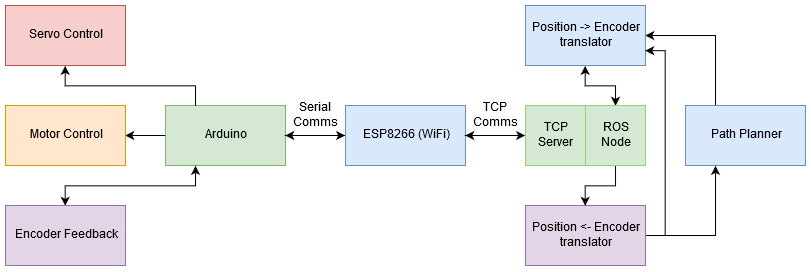
The software system used to control the robot is fairly involved. A diagram of the software structure used to control the final iteration of the Inkscape robots is shown above. The code is located on GitHub, and is fully documented. It consists of two main sections, the low-level controls happening on the Arduino itself, and the higher-level controls happening on the computer. The Arduino controls the motors via a PID loop using encoder feedback; it receives data from the encoders themselves using Interrupt Service Routines (ISRs). Finally, the pen mounted to the robot is controlled via a servo. This can be seen here. The PID loop takes its target encoder values from the higher-level controls happening on the computer. The communication between the Arduino and the computer is achieved via an ESP8266 chip. The ESP8266 acts as a relay between the computer and the Arduino; it receives and stores data from both in internal buffers. It sends data from these internal buffers to the Arduino and computer. You can see the code for this here. The computer communicates with the ESP8266 via a TCP socket - the computer runs a TCP server, and the ESP8266 a TCP client. The Arduino communicates with the ESP8266 using Serial communication via the TX/RX pins. The Arduino will send encoder data through the ESP8266 to the computer. Once the computer receives the data, it will pass it to a ROS node that will decode it into a coordinate position, so that the ROS system knows where the robot is in (x,y) space. This is done here. After being decoded, a path planning node (seen here) will determine what target (x,y) coordinate the robot should move towards, based on where the robot is currently, and what position in the path the robot needs to move towards next. Finally, another translator ROS node (seen here) takes the desired (x,y) position, and converts it back into encoder values, using the current position, current encoder values, and desired position information. To make it easier to launch this complicated node setup on the computer side, a launch file is used. The launch filed used to run the latest implementation is located here.
Electrical Subsystem
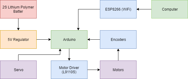
The electrical stack on the robot is relatively straightforward. A 2 cell lithium polymer battery powers a 5V regulator rated for 5 amps. 5 Volt power is then given to everything except the motors and WiFi chip. The motors are powered through the motor driver, and the WiFi chip receives 3.3V power from the regulator built into the Arduino. The circuit diagram for our system is shown below.

Mechanical Subsystem
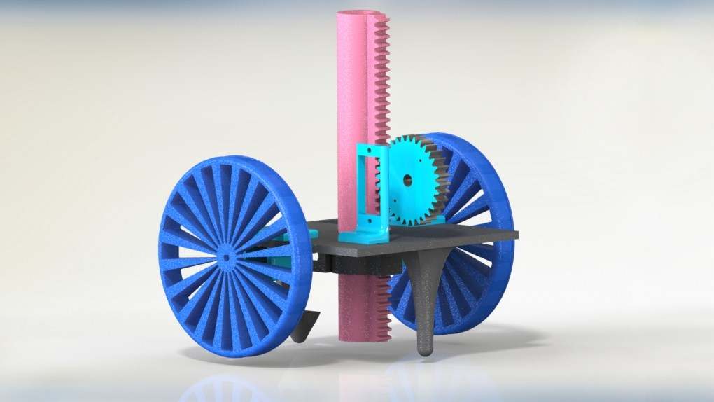
The robot’s low cost, 3D printed body had a few primary components: the chassis, housing, pen holder/manipulator, and component mounts. The chassis itself was a simple base for everything to bolt into and for the pen holder to slide through. Its very square shape allowed a housing to easily integrate with the chassis. Also, there were extruded nubs on the bottom of the chassis to prevent the robot from tipping over. The pen holder used a servo to control a rack and pinion, raising and lowering the pen. Finally, a mounting system for all the electronics was placed on the rear of the robot to give the battery a spot to sit and mounting holes for the protoboard. Everything on the chassis had a place.
Budget
You can build Inkscape yourself for less than $250; building all of our iterations of Inkscape took us $201.80 in total. We have included a detailed breakdown.
| Name | Quantity | Cost/Unit | Total Cost |
|---|---|---|---|
| Wifi Board | 2 | $6.95 | $13.90 |
| Motor/Encoder | 4 | $14.52 | $58.08 |
| Motor Driver - 5 pack | 2 | $7.49 | $14.98 |
| Pen Servo - 6 pack | 1 | $11.99 | $11.99 |
| Lipo Battery | 1 | $11.99 | $11.99 |
| Arduino Nano | 1 | $11.19 | $11.19 |
| Perma Proto | 1 | $12.51 | $12.51 |
| TB6612 Motor Driver | 1 | $3.95 | $3.95 |
| Jumper wires | 1 | $3.40 | $3.40 |
| Arduino Nano (different version) | 3 | $9.99 | $29.97 |
| 5V Regulator | 1 | $14.95 | $14.95 |
| NRF24L01 WiFi Module | 1 | $5.99 | $5.99 |
| Female pin headers | 1 | $5.90 | $5.90 |
| $201.80 | |||
What We Learned: Words of (Questionable) Wisdom
We learned a lot over the course of our eight-week journey. We learned that iterative development is super hard! We learned that one of the things that can make iterative development easier/more successful is better anticipation and mitigation of risks; although we acknowledged that WiFi communications were going to be a risk, we didn't get started early enough to be able to successfully mitigate this risk. This ended up being somewhat of a pattern for us, which ultimately prevented us from reaching some of the goals we hit.
However, not all hope is lost, because one of the major strengths of iterative development and one that we definitely wielded to our advantage, was the ability to pivot. Whenever something went wrong, we were able to pivot to course correct--not exactly to the same course, but to one that still would get us to our MVP. This is evidenced in all of the changes to our electrical subsystem and software architecture.
Finally, we learned the importance of communication. Eight weeks is the longest time we've worked on the same team on a technical project, and there were a slew of communication challenges associated. We've learned about the importance of transparency with one another, especially when it comes to our expectations, goals, and desires for our project. We benefited greatly from our deliberate and intentional attempts to be transparent and honest with one another.