Moving on from sprint 1, our team prioritized finalizing our punching mechanism, creating a working x-axis gantry, and full integration with software. For our punching mechanism, it was pretty clear that what we had developed in sprint 1 wasn’t going to work. The rack and pinions were challenging to get lined up in our 3D printed housing and the slightest misalignment led to a excess friction. And the solenoid we had first tried wasn’t strong enough to punch through the paper. Moving forward, we decided to investigate two other punching mechanisms. One that used a larger solenoid using the same needle from the rack and pinion and one that relied on a servo to rotate and an arm to make a dent in the paper. We ultimately picked the large solenoid mechanism because of the consistency of the hole it could make. We originally planned to make three holes at one time but to be able to use the large solenoid we decided it would be easier to develop a gantry system.
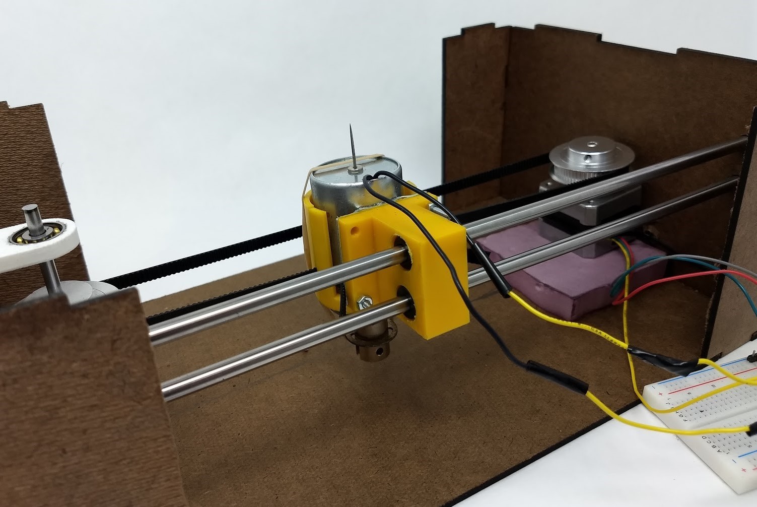
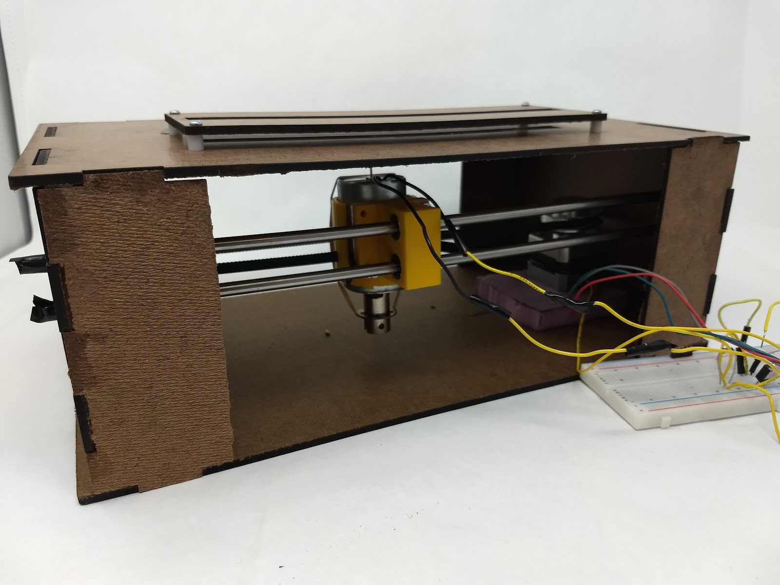
For our x-axis gantry, we designed a solenoid holder that would house the solenoid and allow it to slide along two bars that ran horizontally across the box. Using purchased drive belts, bearings, and pulleys, we set-up a stepper motor to drive the belt. The belt was cut to size and fitted into the solenoid holder. This gantry set-up allowed us to move the solenoid along the two shafts, however, there was significant friction from the large moment arm of the solenoid hanging off the shafts. The stepper motor was able to overcome this friction but we knew this was an element of the system we would want to redesign in the next sprint. To hold the newly developed gantry and punching mechanism, we laser cut a hardboard box with a lid that would allow the needle to puncture the paper.
To prepare for integration, we began by setting up an LED circuit where the blue LED represented solenoid punch, green represented x-axis gantry movement, and red represented y-axis movement. This allowed us to visually confirm the command sent from the Arduino were the expected output given the song. We were then able to translate the LED commands into motor commands to control the punch of the solenoid and x-axis movement when the housing from the mechanical system was assembled. We calibrated the speed of the gantry and space between punches for maximum readability of the braille readout.
In this sprint, we also worked on improving documentation. Originally we were making a new google doc for the meeting minutes of each day but this was a barrier to recording the events that happened in smaller meetings that didn’t need a whole google doc. To resolve this, we created a consolidated meeting documentation file with a table of content to make it easy to find the most recent updates. Specifically on the software side, the full music braille identification has been accomplished where rhythm, pitch, octave and accidental recognition implemented and sent in that order. In addition, we were able to build a user interface that would allow the user to select songs through raspberry pi and trigger the arduino to punch the corresponding song. Since our target for this project is people with visual disability, we also implemented speech that would read the song titles as the user scrolls the songs.