For each successive sprint, we added an additional component of our mechanical system. We started with the punching mechanism, and then moved on to the gantry, and the roller. Each component added a degree of freedom to our project.
The punching mechanism was the first mechanical component of our project that we prototyped. We originally wanted to create a raised dent in the paper, like the braille printed by industry embossers. In our initial tests, we tried blunt needles, small rods, and wire attached to a 4V solenoid to create the dent. The small solenoid was too weak to dent the paper. We then tested a sharp needle, which was able to punch all the way through the hole after consecutive hits to the paper on the solenoid. After discovering the needle could create a raised perforation in the paper, we decided to move forward with the needle as the MVP hole maker. After deciding to use the needle, we knew we needed a strong mechanism to push the needle through the paper than the solenoid.
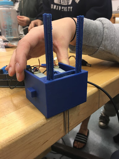
The next system we tried was a 3D-printed PLA rack and pinion with the needle secured a groove in the rack. This was strong enough to punch through the paper when powered with a DC motor. The mechanical deliverable we produced for sprint 1 was housing that contained two rack and pinions with needles attached. However, we found that securing the rack and pinion in the box was quite challenging. An unfortunate combination of 3D printed tolerance and slipping gears made it difficult to get both mechanisms running smoothly.
Moving forward into sprint 2, we decided to overhaul the punching mechanism to push the needle through the paper. Trying to translate the rotational motion of the DC motor to linear motion with the rack and pinion was over complicating things. We discovered a box of 24 V solenoids in the ECE stockroom and went back the solenoid testing we did in sprint 1 with a stronger solenoid. This worked much better and we were able to attach the needle to the spring internal to the solenoid. Then we 3D-printed a casing t hold the solenoid on. After finalizing our punching mechanism in sprint 2, we didn’t make an modification to the punching mechanism in sprint 3.
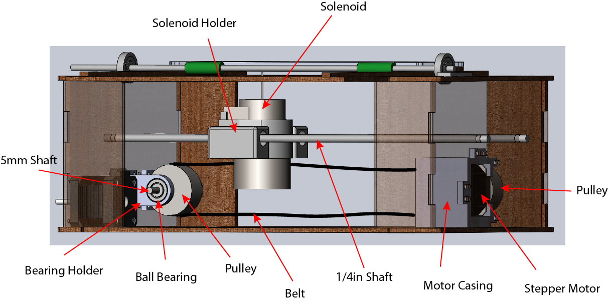
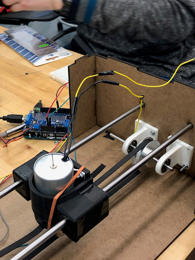
In our first run of the gantry, during sprint 2, we secured our punching mechanism, the solenoid, to two shafts, one above the other. We secured a belt to the solenoid, and the belt went around one pulley attached to the wall and another pulley attached to the stepper motor that moved the gantry. We wanted to have a working gantry by the end of the sprint, so we did not have time to design and 3D print a motor casing, and instead used foam to hold the motor at the correct height. When testing our gantry, we discovered that the torque from having the solenoid only supported from one side made it difficult to move the gantry.
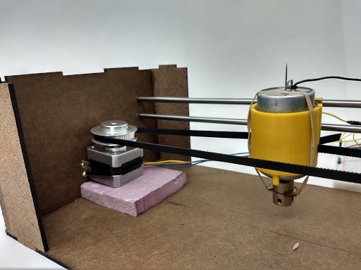
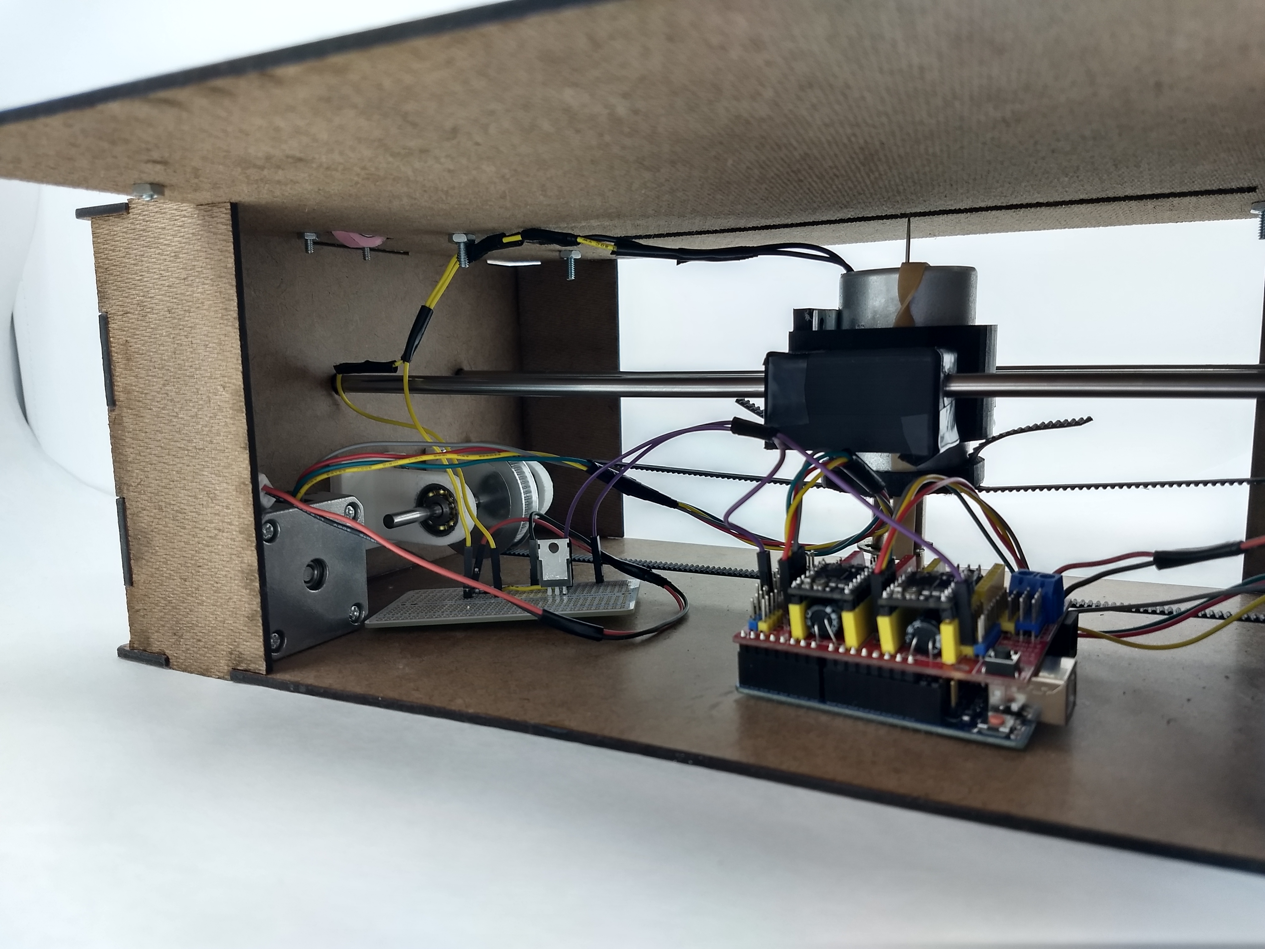
In our second run of the gantry, during sprint 3, we modified the position of the shafts and the casing that held the solenoid to reduce torque. We put the shafts on either side of the solenoid, and rotated the two pulleys attached to the belt by a quarter rotation. This made the gantry run much smoother, and reduced the force on the motor.
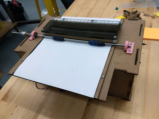
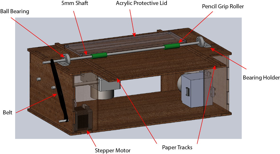
To move the paper, and achieve the third degree of freedom for our machine, we used a roller in sprint 3. The roller is controlled by a stepper motor that microsteps. The paper is constrained on the two longer sides by tracks to ensure the paper stays straight. When first designing the roller, we were envisioning two rollers on either side of the protective cover. However, we realized that having a second roller was unnecessary, since the first roller would be able to move the paper, and having the protective lid on the housing would prevent the paper from folding once it had been inserted. The pencil grips are slightly too large for the 5mm rod that we used for the shaft, so we wrapped the shaft in tape to secure the pencil grips. We had to adjust the tape inside the pencil grips, because they were uneven at first. This caused the paper to rotate as it moved forward through the roller, and was not the desired outcome. After re-taping, the grips work well to move the paper linearly, and also hold the paper in place while punching.