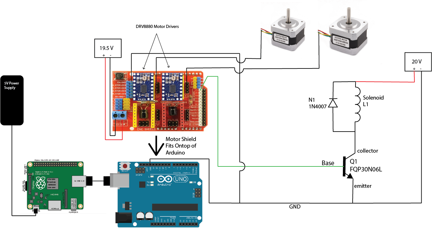
In terms of our electrical system we used the Arduino CNC V3 Motor Shield in order to run the stepper motors which rolled the paper back and forth through the printer and moved the solenoid side-to-side on the gantry. This motor shield fit snuggly right on top of the Arduino Uno we used and was powered by a typical 19.5 V wall power supply.
In order to control the punching of the solenoid we used an Nfet to regulate whether it was powered or not. In order to power our solenoid, we used a separate typical 20 V power supply. The positive lead from this is connected to the solenoid and a flyback diode in parallel. The purpose of this diode is to prevent high voltage peaks from damaging the transistor, and it is generally used in circuits with different types of inductors. The current flows through the solenoid and into the collector of the transistor and then to the emitter which leads to ground. However, current is only allowed to flow through here if a minimum voltage is reached at the base of the transistor. This is provided by digital pin 11 on the Arduino (accessed via the z+ pin on the motor shield). With this, we can activate and deactivate the solenoid (make it punch up or let it fall back down) with the setting of pin 11 on the Arduino to high/low respectively.
The Arduino CNC V3 shield works with DRV8880 motor drivers to control the stepper motors. The motor drivers have the capability of microstepping which is determined by the current across the potentiometer which can be adjusted by changing the resistance across the potentiometer and measuring the voltage. Based on the formula found on the Polulu website, we set the motor drivers to microstep at ⅛ of a step.