What exactly have we been doing for the last two months?
Coming up is a sprint-by-sprint description of the work that the EduPOE team
has been doing to create our aeroponic garden.
Sprint 1
The main goal of this sprint was to get a basic idea of what the system would be and really understand how the pump would work because without that, there is no aeroponics. We made a static mechanical structure and got the pump working and integrated with the computer. We also wanted to learn more about aeroponics and growing in general.
Electrical
X
Sprint 1 Electronic Schematic
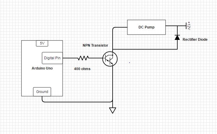
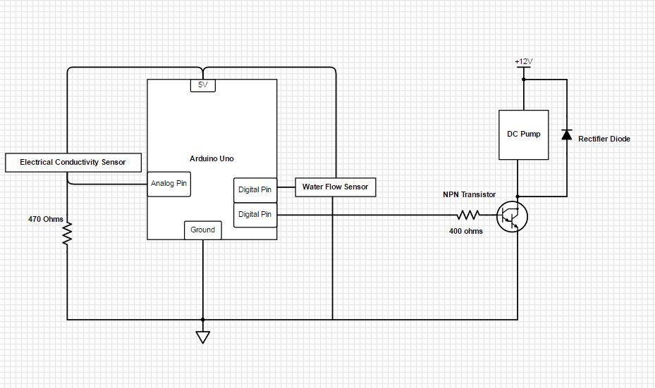
The main electrical goal for this sprint was to choose, power, and control a pump. Our first pump choice was a 120 V AC pump which we wanted to control with a self-built relay box. After determining that powering 120 Volts so close to water was not ideal for our project we switched to a 12 Volt DC pump. We briefly built a transistor switch to control the pump (schematic right), but due to issues with our flyback diode we switched to an arduino motor shield for control purposes.
Software
During this sprint, our main software goal was just to get the pump communicating with the website as a proof of concept. Because we ended up using the motor shield this sprint, we were able to use the dc_motor_test.ino that was sourced from the motor shield's test code page
Mechanical
X
Our First Mister Design!
On the mechanical front, our primary focus was to source a pump for our system and prototype a mister. After we 3D-printed one set of misters (shown left), we discovered the 3D-printers don’t print nearly accurately enough for what we’re trying to achieve–the parts really do need to be cast, which we don’t have the equipment to do. Secondly, we now understand that moving forward, we will be working on a low pressure aeroponics system. If we are interested in moving to high pressure system, we will have to first purchase higher-intensity misters and then get a nicer pump, if they require more psi.

X
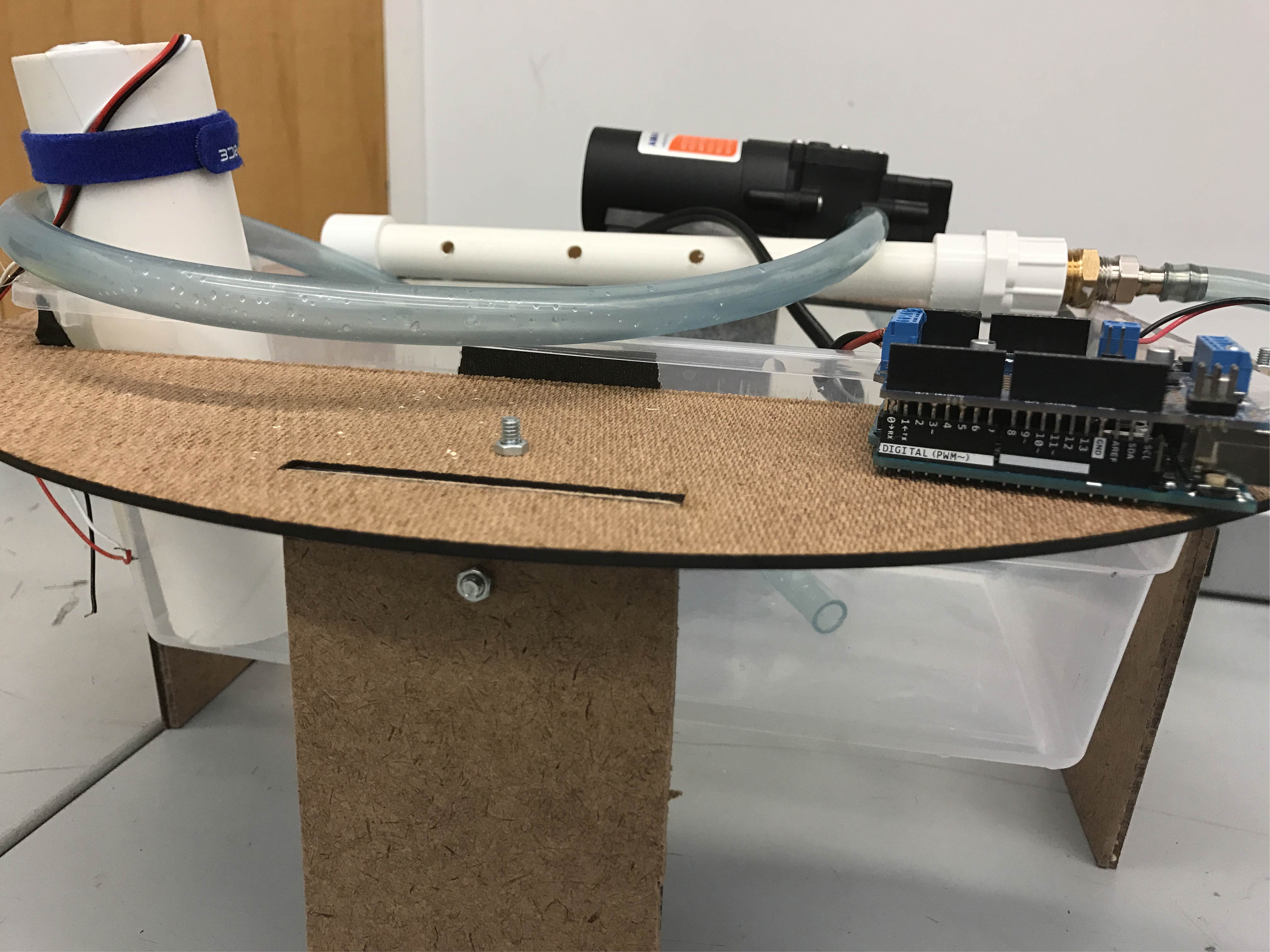
Our Pump!
We also bought a pump (shown right) and a lot of tubing and PVC connections to go along with the pump and eventually connect to a piece of PVC that will connect to misters. The pump has 3/8" connections and the PVC is 1/2" so we needed to get connections to allow for this.
We also now have some questions about how much power we are going to need. If there are several misters throughout the system that map to each plant, water is going to be diverted through multiple tubes and the pressure is going to decrease. As a result we are starting to toy with the idea of a mechanical design where we only need one mister for all the plants.
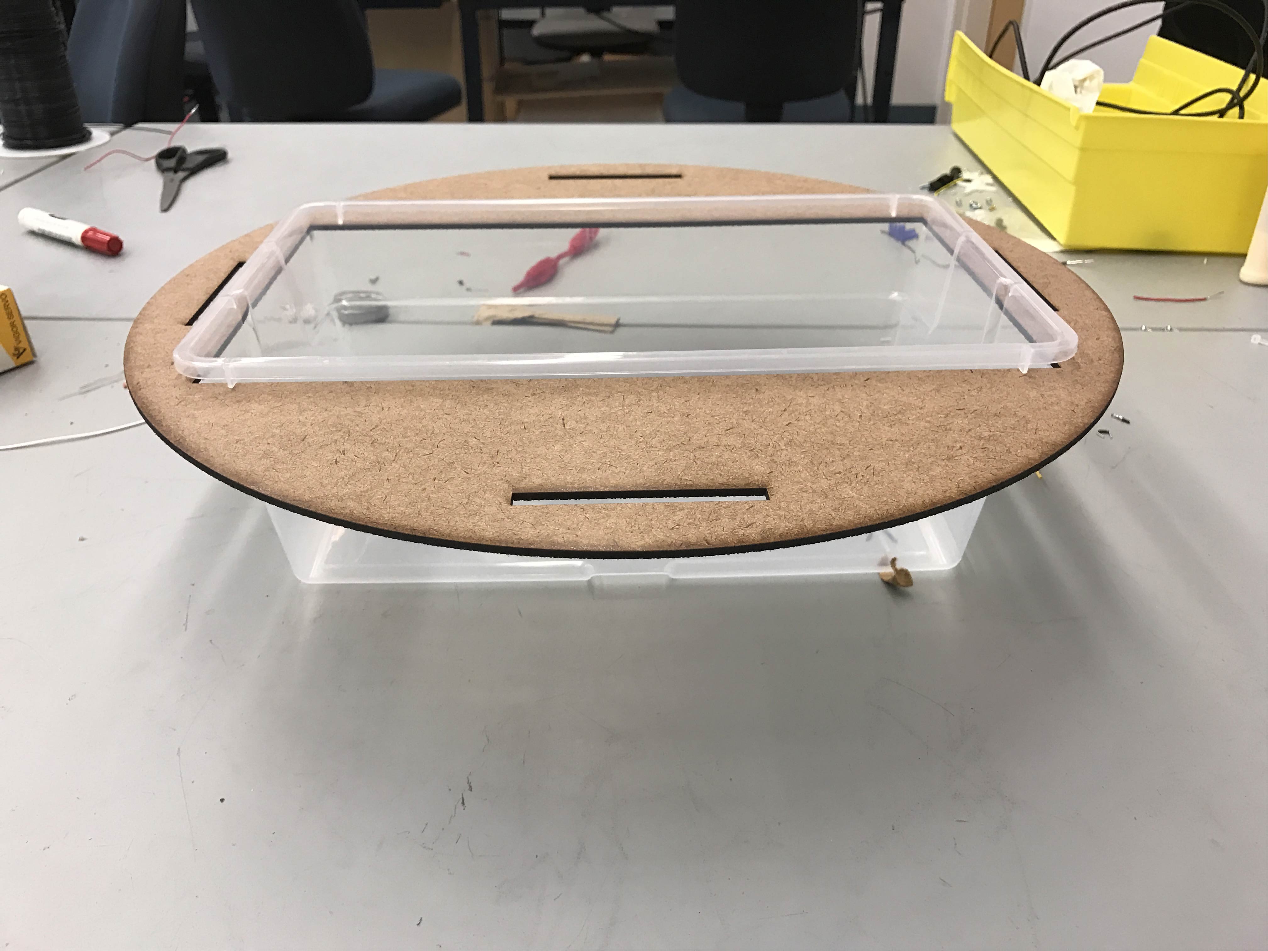
X
The main mechanical structure for the sprint one
The final element of the mechanical design that we worked on was the structure of the housing for the plants (shown left), however we did not want to spend too much time on this aspect of the project until we got the pump working. We designed and a laser cut a circular table top and legs to hold a container of water above the ground. The design is not very sophisticated or structurally sound, but it begins to demonstrate the direction we will be taking the design in the next sprint.
Sprint 2
In this sprint we moved ahead with a more complex mechanical system and continued to add sensors. By the end of the sprint we had a functional dry-running system with a moving mechanical structure.
Electrical
X
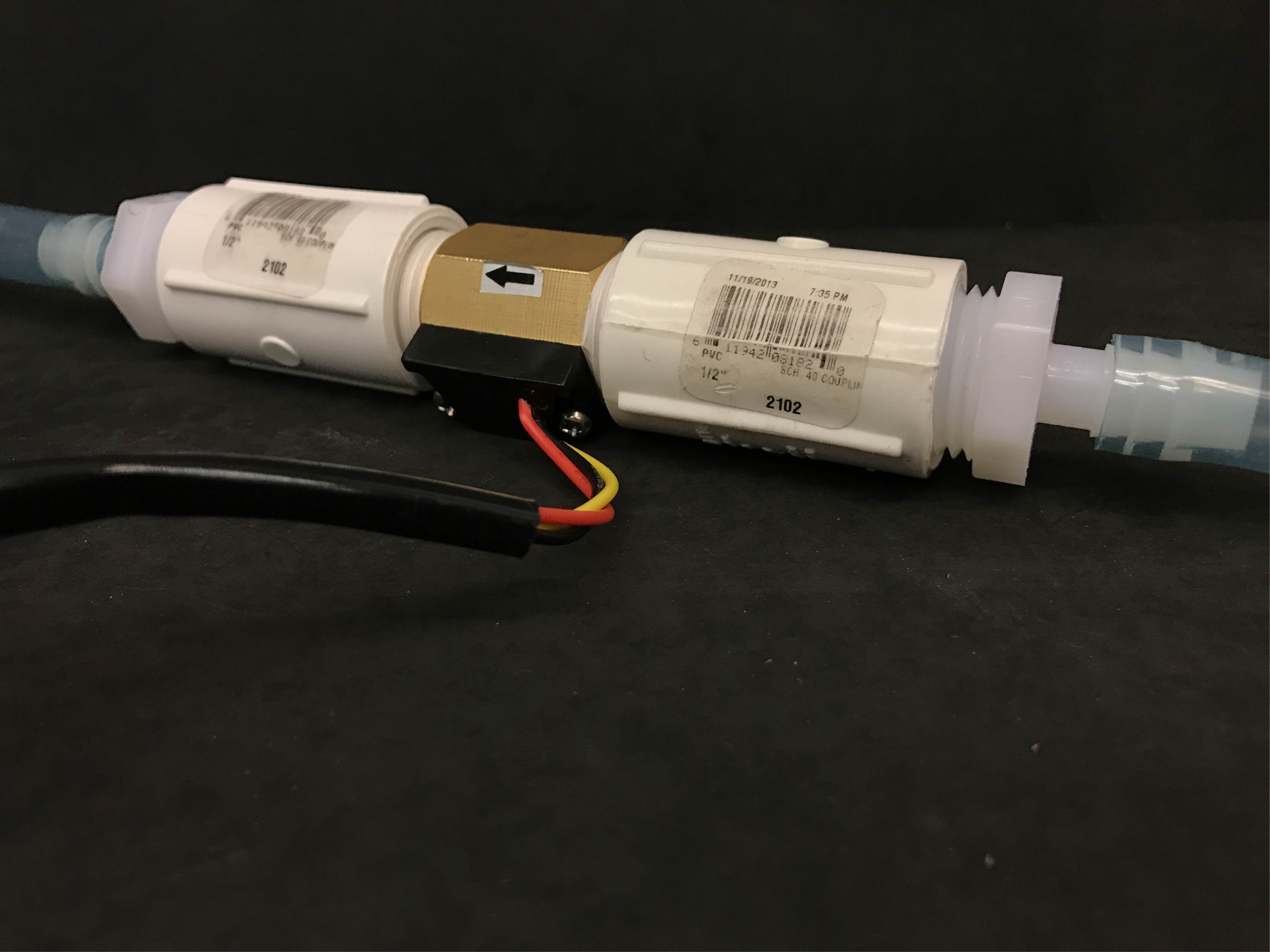
Our flow sensor
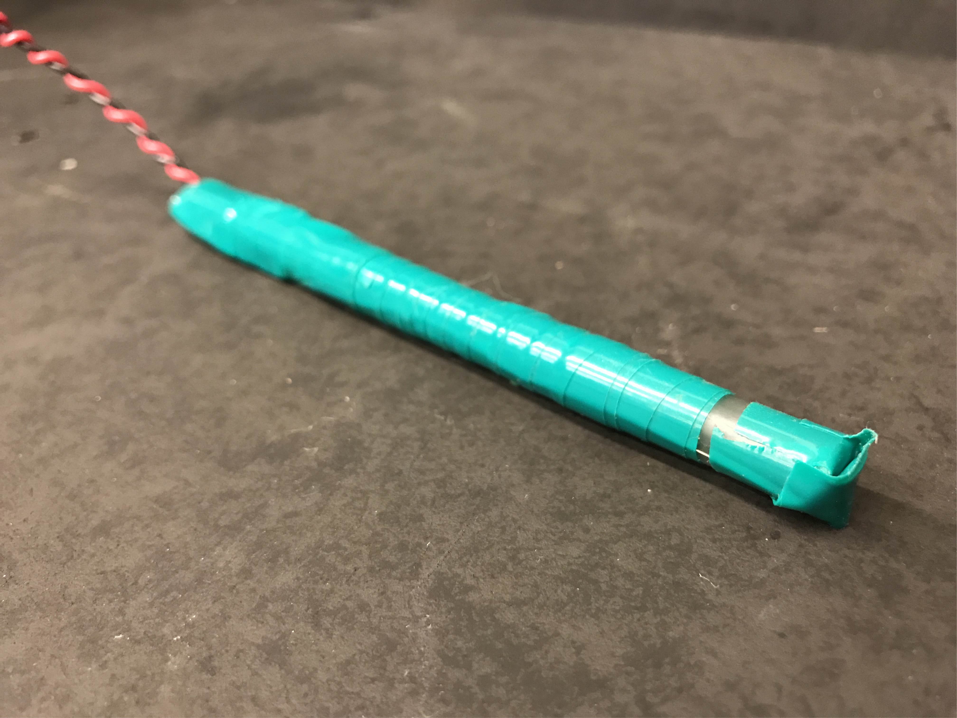
The goal on the electrical front was to implement sensors that would monitor the system’s water and nutrient levels and use feedback from these sensors to control the pump. The first sensor we implemented was a water-flow hall sensor (shown right). Water turns a rotor which creates pulses of electric current that sends a digital signal to the Arduino. The second sensor implemented was an electrical conductivity sensor, made with 10 cm lengths of nichrome wire that are spaced about 1 cm apart on the end of a pen (shown left).
X
Our Electrical Conductivity Sensor
This sensor works by measuring the amount of voltage across the two wires over a period of second and then converting that number into volts. The information to build this sensor and the code used to run it, was modified from this awesome teaching activity. We had originally planned to implment a water-level sensor, but instead decided to use two EC sensors to check for a too high and too low water level.
'
'
X
How we powered our pump this sprint
The sprint two schematic can be seen below:
X
How we powered our pump this sprint
Software
The software portion of this sprint attempted progress in two areas: beginning control code for the pump and sensors as well as working on communicating to Arduino via ethernet.
The pump control code was incrementally written after each sensor was installed. The EC sensor has an analog input and with the help of this awesome teaching activity we were able to take their source code and modify it to only read and output the level of electrical conductivity. We also needed to produce code to measure the flow rate of the water through the hall sensor that we purchased. We used the source code from this website and added in control code to turn the pump on and off at appropriate intervals while checking the water flow and electrical conductivity sensors for potential clogs or leaks. If there was any issue, the pump switched off. If you're interested, you can check out the final version of this code
here under hall_sensor_pump_control.ino.
Due to the late arrival of the ethernet shield, the majority of the first week of this sprint was spent doing preliminary research around how to connect the Arduino to the internet. Unfortunately, once we did recieve the ethernet shield, we encountered consecutive hardware failures that prevented much progress in this area. Next sprint we were hopeful that we would resolve this issue get the Arduino and website talking to each other.
Mechanical
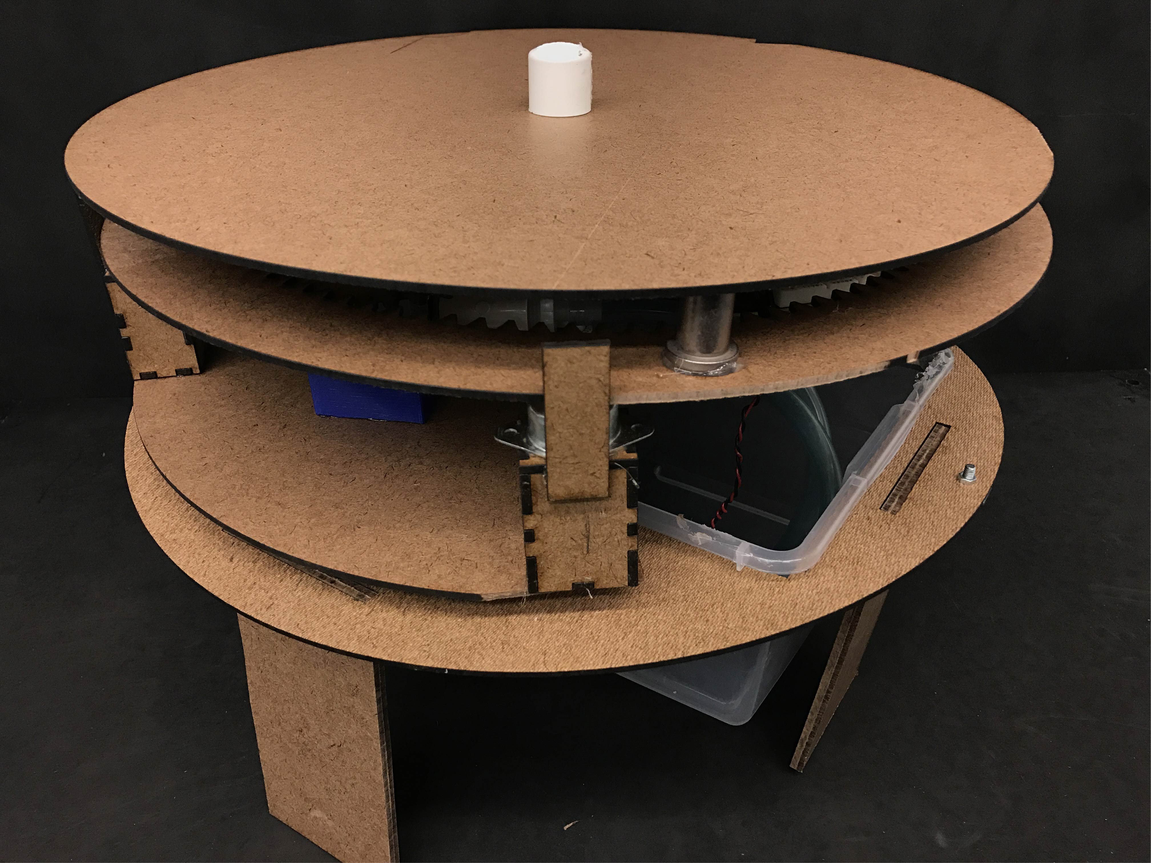
X
Our Sprint 2 Design!
X
Our Lights!

This sprint, the main mechanical goal was to brainstorm final designs, weigh each option, and then mock-up the chosen design.
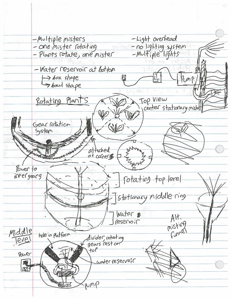
We did this by having each team member create three designs, and present each to the team. Then, we chose three to flesh out. The mechanical sub team created detailed drawings for each chosen design, and then presented them to the whole team. Together we settled upon a design that consisted of multiple plants and one mister, so as to keep up pressure in the mist. In order to have one mister and multiple plants, we decided to have a stationary mister in the center with plants that rotated around it. Once a design was determined, the mechanical sub team created the design in Solidworks. To prove the feasibility of the idea without having to waste a lot of material, we laser cut the design to be half the size of the actual. After several modifications to the prototype to improve functionality, we laser cut a full size prototype that featured four roller bearings (shown left), which supported a large gear.
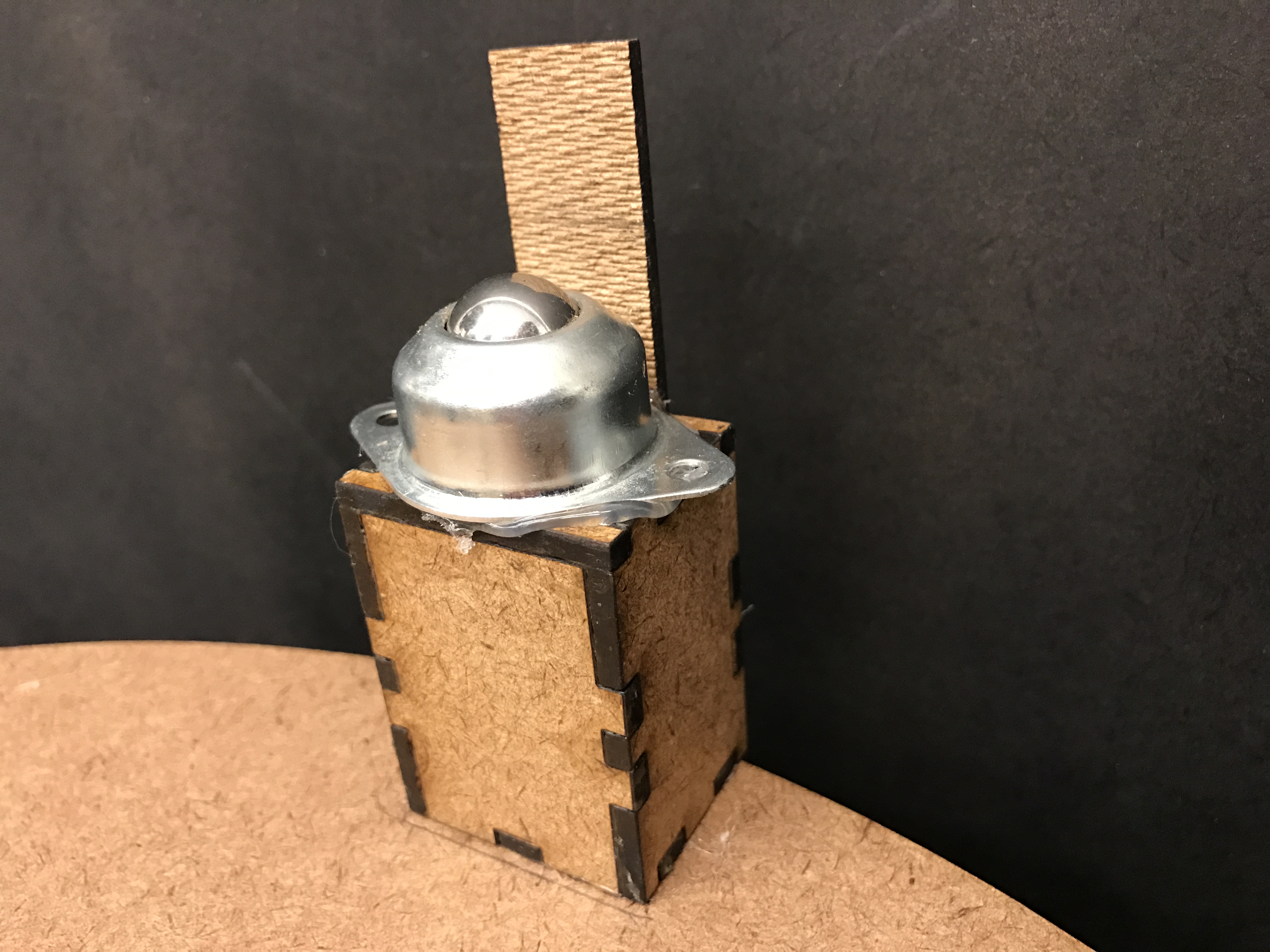
X
Our Caster!
We could not test this design with water, due to the water's proximity to electric components. This design provided a proof of concept for our design, and that we could rotate the plants to a single mister.
Sprint 3
The main goals of this sprint were to water-proof and better the plant-based design. We also wanted to continue to make a more complex mechanical design and implement the website controls.
Software
In this sprint a couple of breakthroughs were to be had on the software front. With an Ethernet shield
now working properly, we were able to continue on to figure out how to log data to a google sheet with
PushingBox's API, embed a graph from that sheet into a web page, and also link buttons and fields to the
NearBus API with javascript and jQuery for full two-way communication between website and Arduino.
Electrical

X
Our Lights!

X
Our Nutrient Drip System!
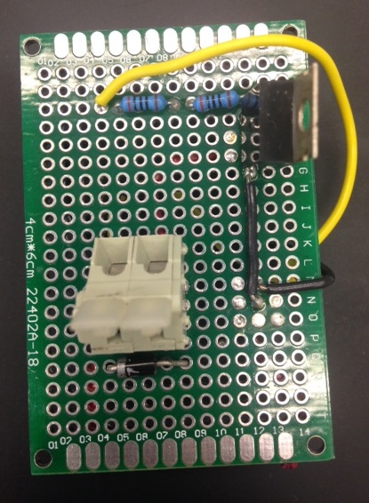
The goal in the electrical subsystem for this sprint was to clean up integration with the mechanical system and add switches to some of the controls. We also added in LED lights (shown right), which are at a wavelength to encourage plant growth, and a solenoid valve (shown left), which controls a nutrient drip systen. To clean the electrical design up, all sensors and switches were soldered onto protoboards and all wires clearly labelled. Each board was tested and tweaked as appropriate. Although the transistor switches for the led lights did not require flyback diodes they were added to the protoboards for modularity.
Mechanical
X
Sprint 3 CAD!
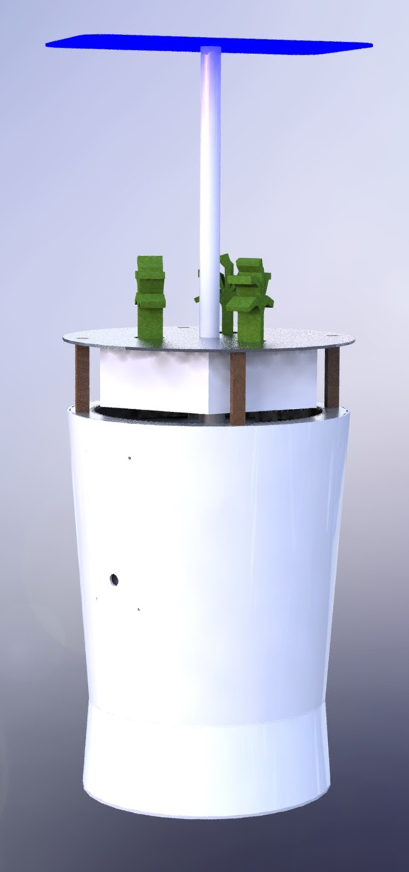
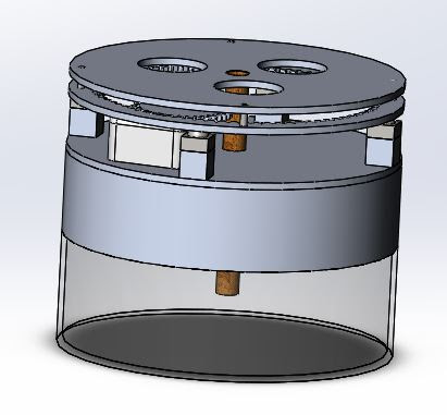
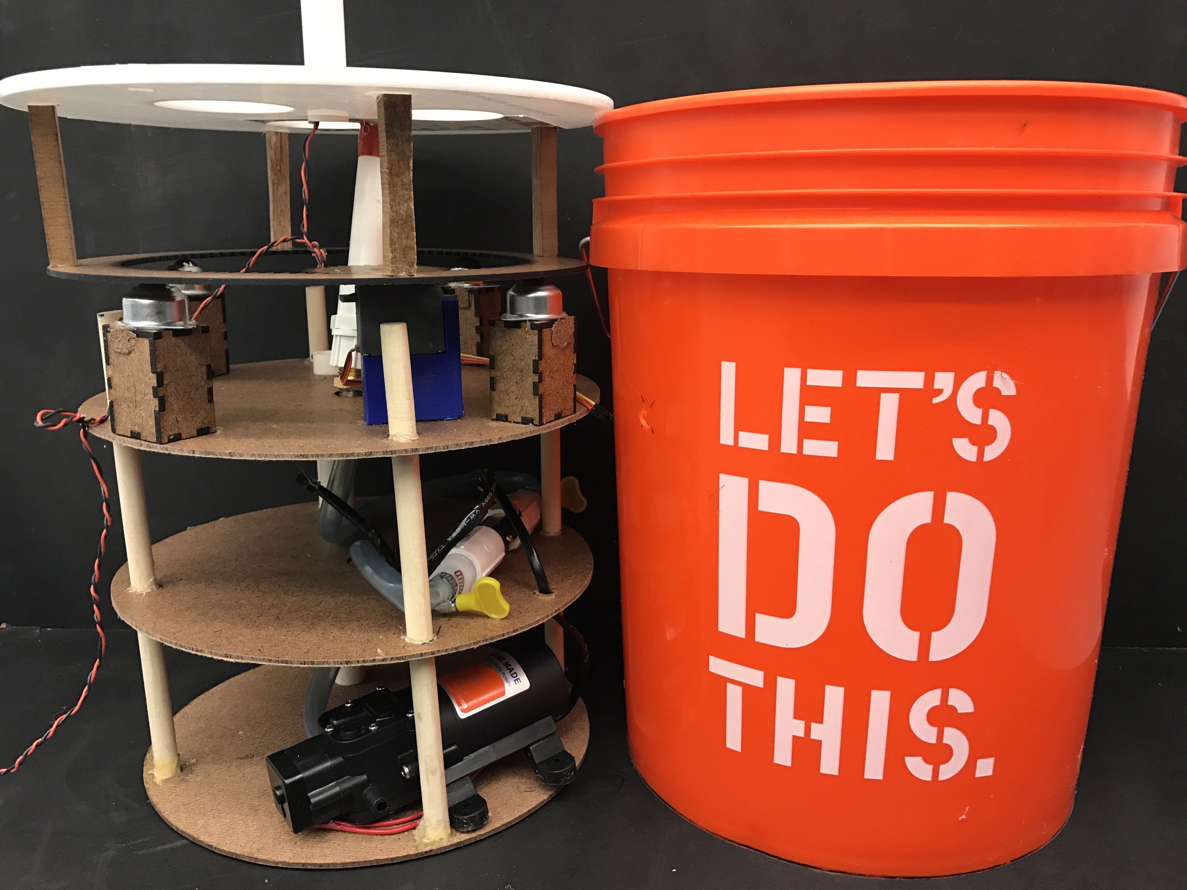
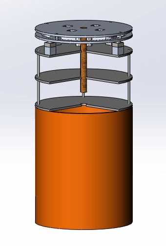
During sprint three we wanted to progress the mechanical design to a point that we could run a wet system for testing purposes. To achieve this we first decided that we take our tiered, rotating system from last sprint and mount it inside of a 5 gallon bucket (this housing is shown on the right). We made a 4 tiered system to create more space for components to fit. Going from top to bottom we had a level to house the plants on the rotating table, a level to mount the servo that drives the rotation of the plants, a level for the Arduino and associated electronics, and a level for the pump and tubing. Below all of that is the water. While there was more space for components than in previous sprints, we still overlooked several important elements of the system. The tubing needs more space to bend so that it will not kink. The nutrient pump system that we designed this sprint is too big to fit inside the bucket. Overall wire management is still a hassle. We needed to be smarter about how we design with other components of the system in mind. Finally, made worse by the fact we were using a bright orange Home Depot bucket, the system was not very pretty and our target project goal is a high degree of finish.
Sprint 4
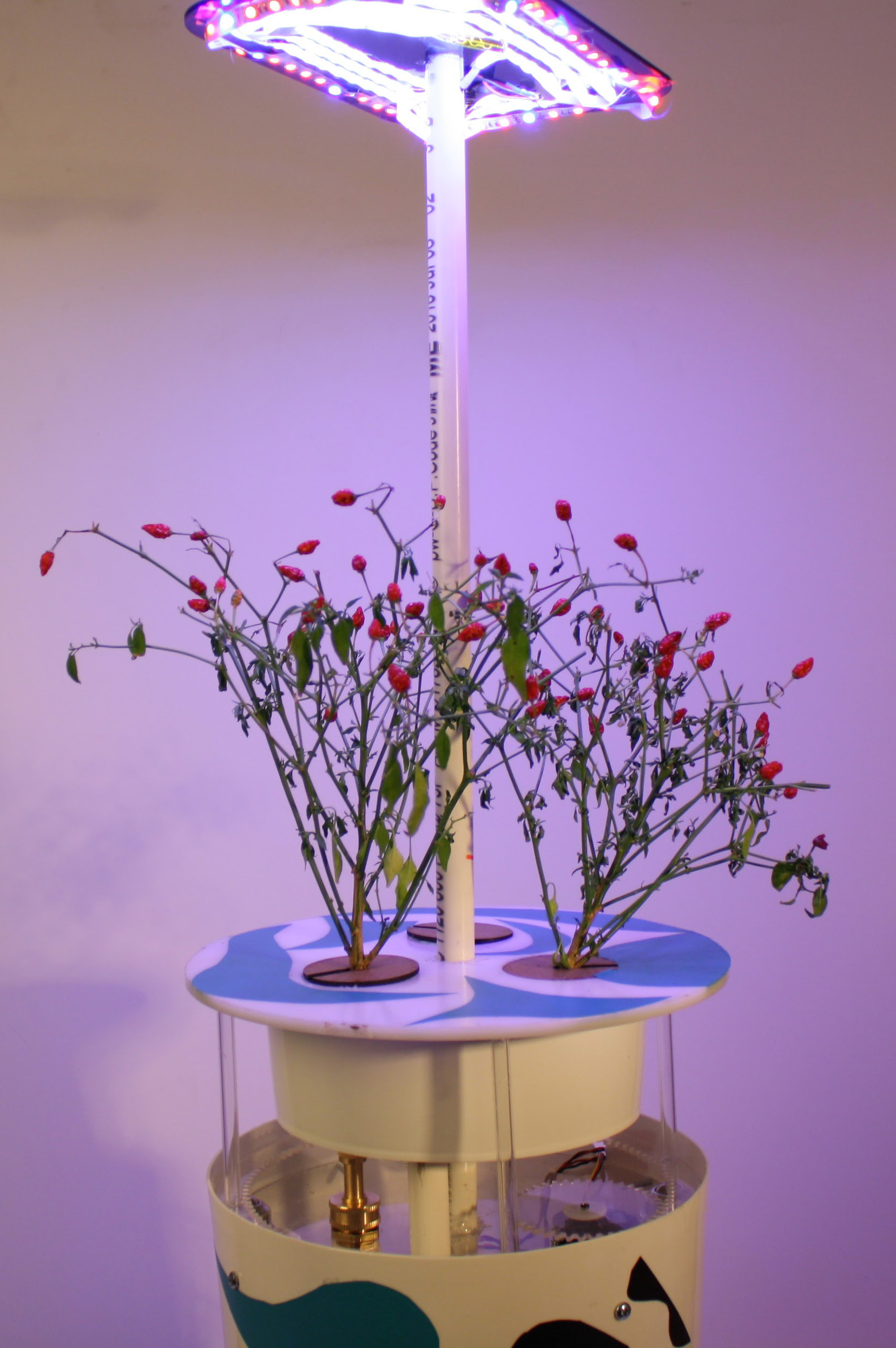
The goal of this sprint was to finish the project. Details of its completion can be found on the Product Page of our website!