How do you make the electrical subsytem of an autonomous Aeroponic Garden?
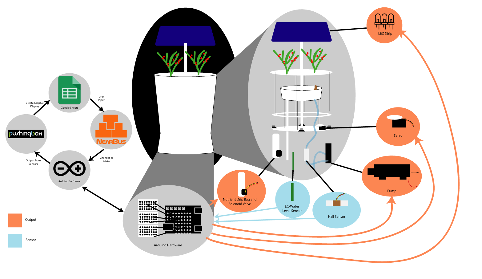
The electrical portion of our aeroponics system consists of sensors to monitor the status of our system and various components to keep the system running. Read on to learn how we created our electrical subsystem.
The Components
First, here is what makes up the electrical system:
- Arduino Uno
- Ethernet shield
- 12V 5A DC Power supply
- 12V 1/4" Solenoid valve
- 12V DC Pump
- 12V Blue and red LED strip
- 12V White LED strip
- 5V Continuous rotation servo
- Sensors
- Hall effect water flow sensor
- Two electrical conductivity sensors
So, how do these components function in the system?
The solenoid valve is important in our nutrient drip system. This is what supplies our plants with the nutrients they need to grow. A solenoid valve is an electromechanically operated valve. The valve is controlled by an electric current through a solenoid. In the case of our two-port valve, the flow is switched on when current is supplied. The pump is a standard DC pump that is used supply water to the misting system. The LEDs supply vital light for our plants to grow. Plants primarily use red and blue wavelengths in photosynthesis so it's is more efficient to directly supply them with these colors. Under blue and red lights plants look a "lovely" gray color. That's why we included the white lights as well.
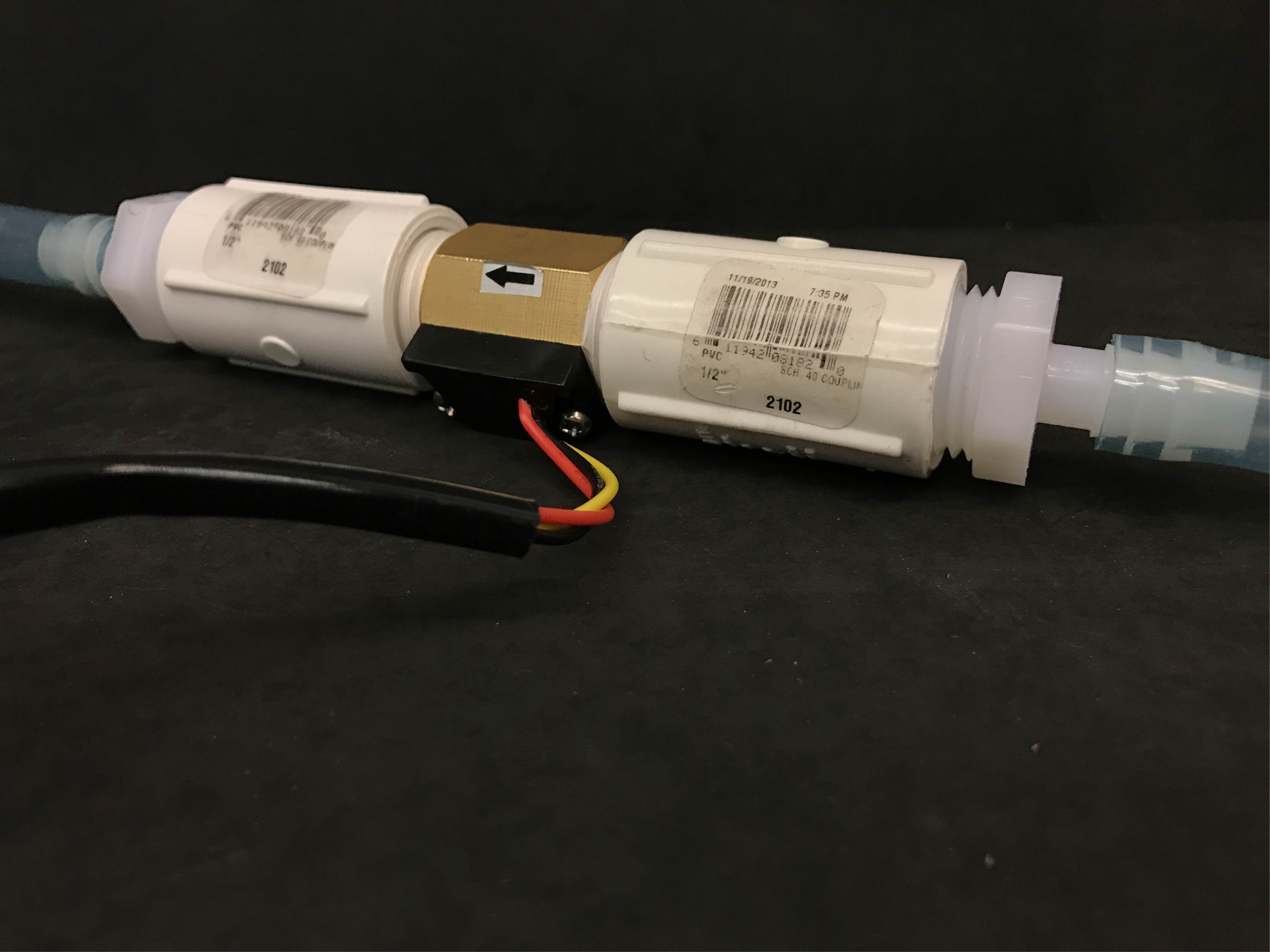
Our flow sensor
Our Electrical Conductivity Sensor
The Circuit
Now that you know about the components let’s talk about how they are all connected.
Our entire system is controlled by an Arduino Uno, with an attached ethernet shield (to connect with the website). Below we will talk about how we connected each of the other components listed above.
Sensors
The electrical conductivity sensor consists of two nichrome wires wrapped around a hollow plastic tube. We simply measure the voltage across the two wires. The water flow sensor, instead of outputting analog values, delivers pulses that are proportional to the amount of water flowing over a given time interval. We therefore need to connect it to a digital pin.
12 V control – transistor switches
Our pump, solenoid valve and LEDs all run off of 12V. However, the digital pins of an Arduino Uno are only able supply 5V. Since we wanted to be able to turn these components on and off with the Arduino we implemented low-side transistor switches. We used the TIP120 NPN Darlington transistor in all our switches. Also, we included a flyback diode to prevent induction from damaging our Arduino. Though this was not a concern for the LED switches, it was important for the solenoid valve and DC pump. The base resistor value was chosen with consideration to the transistor's Hfe (which corresponds to current amplification). The Hfe of our transistors was 1000, so 400 ohms was appropriate to sufficiently protect the Arduino by limiting the amount of current the transistor could draw while still supplying enough current to the loads attached. With this setup, it is possible to switch the components on and off simply by writing to the Arduino's digital pins. See below for the switch schematic.
Power supply
In total, our components draw around 4.5A of current, just under the rating of our power supply. However, the solenoid valve, which draws 1.24A, is never on for more than a few seconds. We feel reasonably confident that our 5A power supply is sufficient for all of our components. To power the Arduino, we use its barrel jack connector. This connector is meant to handle between 7 and 12V (though it can handle up to 20V.) The built-in voltage regulator drops the 12V to the 5V required by the Arduino. Therefore, we didn't need an external voltage regulator for the Arduino.
Circuit Diagram
Here's what the final circuit looks like:
Putting it all together
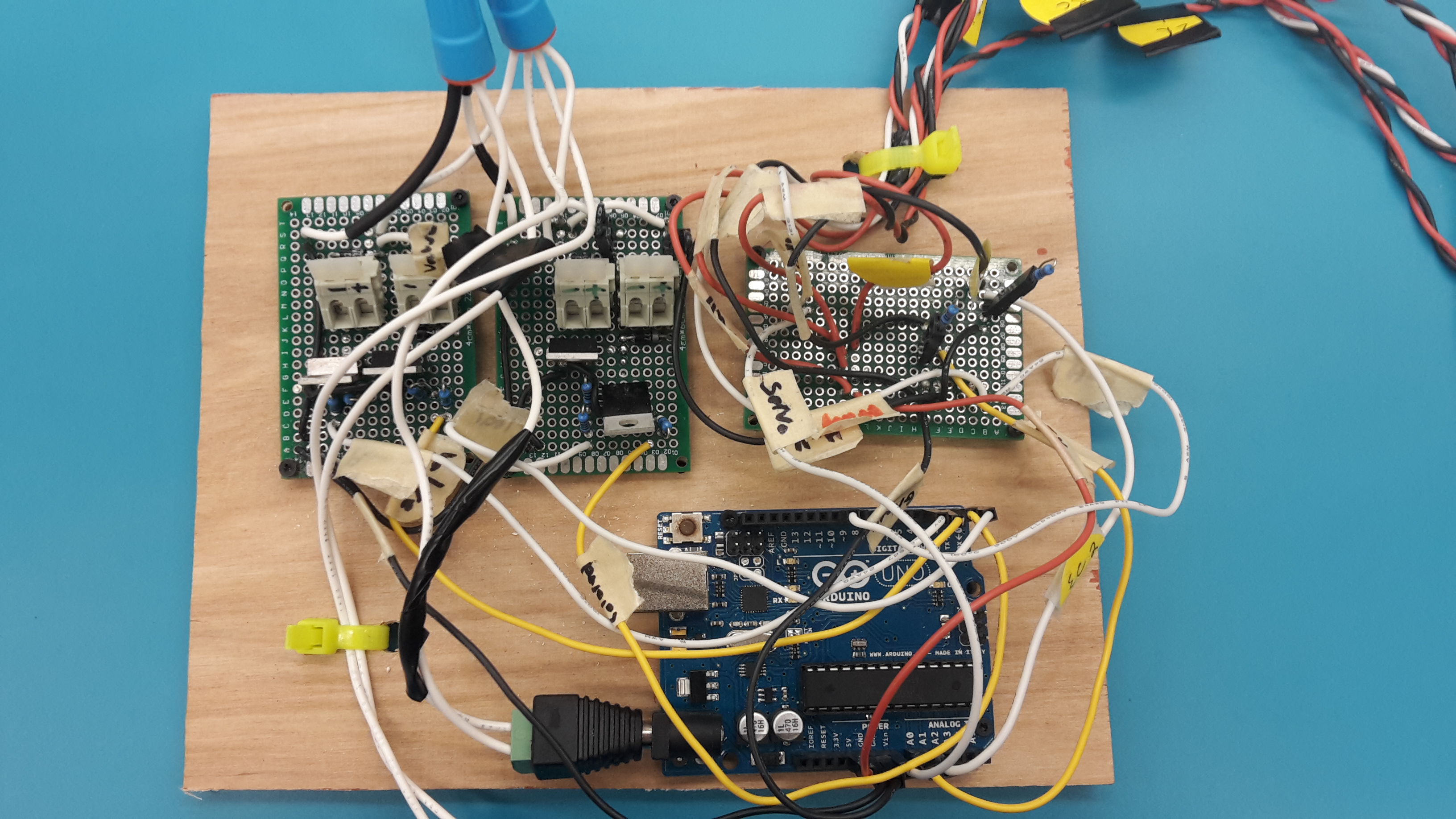
Everything we've just said is great in theory. Here are some pointers for making things work in reality.
The solenoid valve and pump draw more current than most breadboards can handle, so it is necessary to solder their transistor switches. We went ahead and soldered all of our components to a protoboard to make integration easier with the mechanical system. We also labelled each wire with its corresponding component and Arduino pin. This was pretty helpful - we'd recommend it. See below for our final electrical system in real life.