Designing a New Home for Your Plants
The mehcanical subsystem consists of a physical housing for water, rotating platform for plants, nutrient drip system, lighting, pump, and water recycling system.
Components
- 2x 5-Gallon Buckets
- 2-Gallon Bucket
- 4x 1/8" Acrylic Sheets
- 1/4" Delrin sheet
- Screws, Washers, Nuts
- 1/2" PVC
- PVC Fitting
- 3/8" Flexible Tubing
- High pressure mister
- Continuous Servo
- 4x roller bearings
- Sensors
- Water flow sensor
- Electrical conductivity sensors
- Water flow sensor
- Electrical conductivity sensors
Overview
Housing
The entire system fits into a 5 gallon bucket that is then filled with water and allows for easy waterproofing. The electronics that are made to be near water (the pump and the electrical conductivity sensor) are affixed to the main bucket, slightly above the water level. The rest of the electronics are stored in a separate watertight compartment underneath the bucket. This entire system is adorned with decals, to create a modern, elegant design.
Rotating Platform
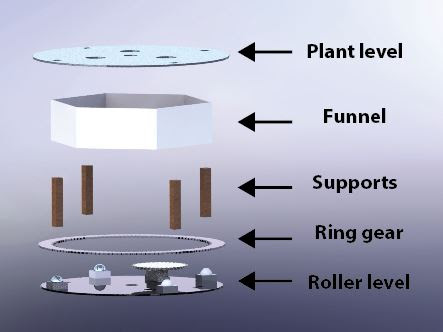
Schematic of Different Levels in the Design
The system can hold three plants in the rotating platform. This top platform allows for the plant stem to be supported above the table, while the plant roots hang below. This table is attached to a ring gear, which allows a spinning motion similar to a Lazy Susan. The gear is supported by four roller bearings, which allow fluid motion. The ring gear is actuated by a smaller gear affixed to a contininuous rotation servo.
The servo and roller bearings are all affixed to a acryllic plate that fits perfectly into the mouth of the bucket. All of these components are modular and can be lifted from the bucket for easy refilling and system are. The plants rotate to the mister head on a timed cycle allowing for an ideal amount of water to be delivered to each plant.
Misting System
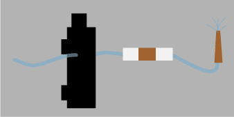
Our Misting System
A 35 PSI diaphragm pump is attached to the side of the housing. The pump has an inflow and an outflow, whick allows water to be transported from the bottom of the bucket to the top. The inflow has a tube attached that routes directly to the water contained in the bottom of the bucket. The outflow routes to the high pressure mister head, after travelling through a hall effect sensor. The water then travels throught the mister head, creating a fine spray that delivers the neccesary water and nutrients to the plant.
Nutrient Drip
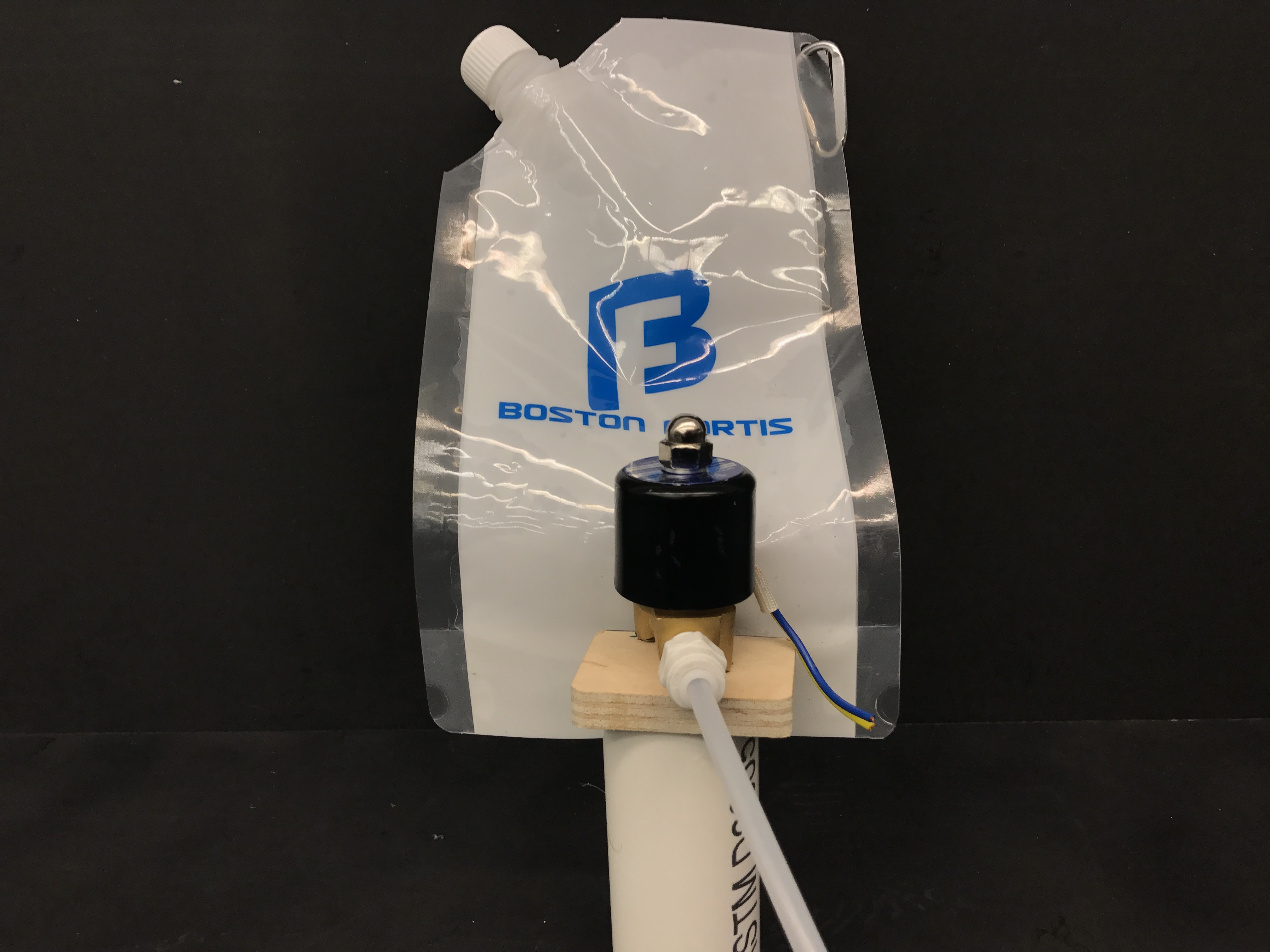
Funnel
As a replacement for the nutrients found in soil, a refillable bag rests inside the housing. This bag holds the liquid nutrients required to keep the plants alive. This bag hold the perfect amount of liquid nutrients for the volume of water the bucket can accomodate. A solenoid valve infuses the nutrients into the water reservoir, where they quickly disperse into the water, and then travel to the plants. The soleniod valve acts as a switch, and releases a flow of nutrients every few days in order to keep the plants happy and healthy.
Water Recycling
Funnel
A funnel is mounted on the inside of the ring gear to catch water, and then return it to the water reservoir at the bottom of the system. The funnel is designed to fit all three of the plants roots, and to fit the mister head.
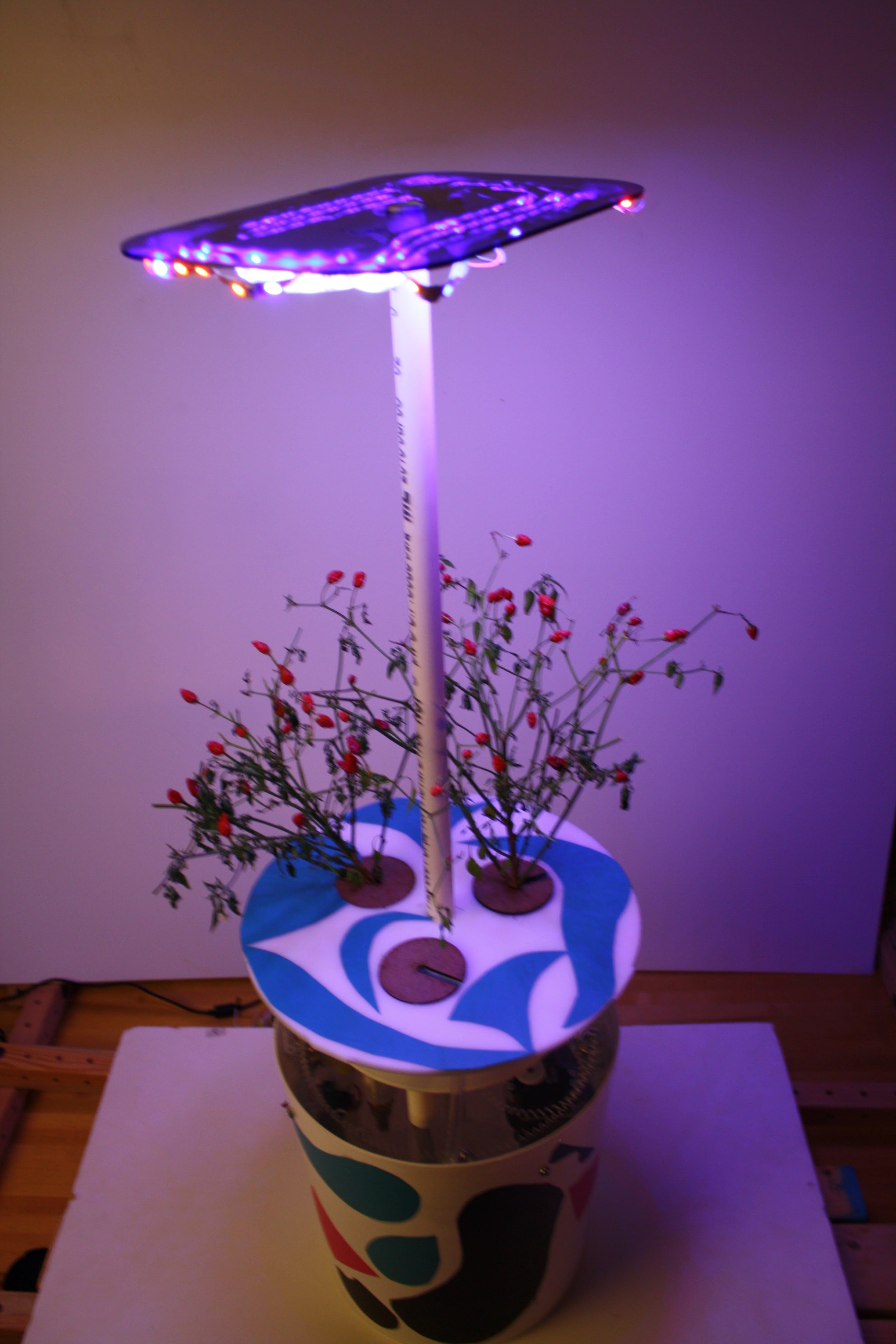
Lighting
A light rests above the plants, changing color throughout the day to simulate day and night conditions and maximize growth.
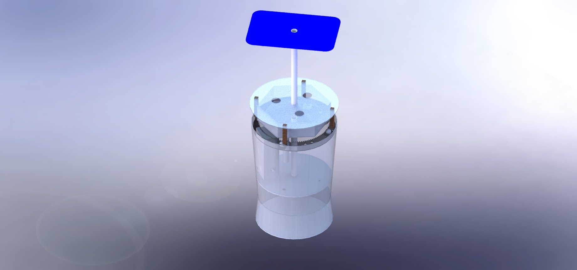
Design
Our Solidworks Housing
The team used Solidworks to design the system. Shortly after the third, two week sprint, we purchased the final materials that we needed to build the system, including acrylic sheets, a continous servo, and two five gallon buckets. We carefully recreated each of these components in Solidworks, in order to ensure each element would fit. The bucket was the most important element in this, since each piece had to be housed inside of it.
After designing the bucket, we created the gears using Solidwork's Toolbox add-in, which makes it possible to easily design gears by specifying the diameter, number of teeth, pitch, and pressure angle. The acrylic sheets are designed such that tubing can run through them and hardware can be mounted easily. The lower level of the system is designed to hold the electronics in a simple, yet subtle fashion while reducing risk of contact with water.
In previous sprints we struggled to create designs that would effectively house every component of the system without creating a mess of wires or tubing, so it was very important to us that our CAD model reflect the physical model as best as possible to account for the locations of individual parts. As such we created a rough model of the pump, servo, tubing, and nutrient drip system to reduce the risk of errors on our part. All in all we designed for ease of installation (connecting electrical components, filling with water), water proofing (making sure no electronics get wet), and portability (making the system compact and easy to transport), while still trying to maintain aesthetic appeal.
Fabrication
Drilling a hole in the bucket
We used a jig saw to cut down two 5-gallon buckets and conneted them bottom-to-bottom with adhesive (system shown right). The top bucket for water containment and wet components is 12" tall and the bottom bucket is 3.5" and contains the electronics. The top bucket was cut due to unnesccesary height, and to improve the overal aesthetic. Later, holes were drilled into the sides of the bucket in order to allow wires to exit the bucket.
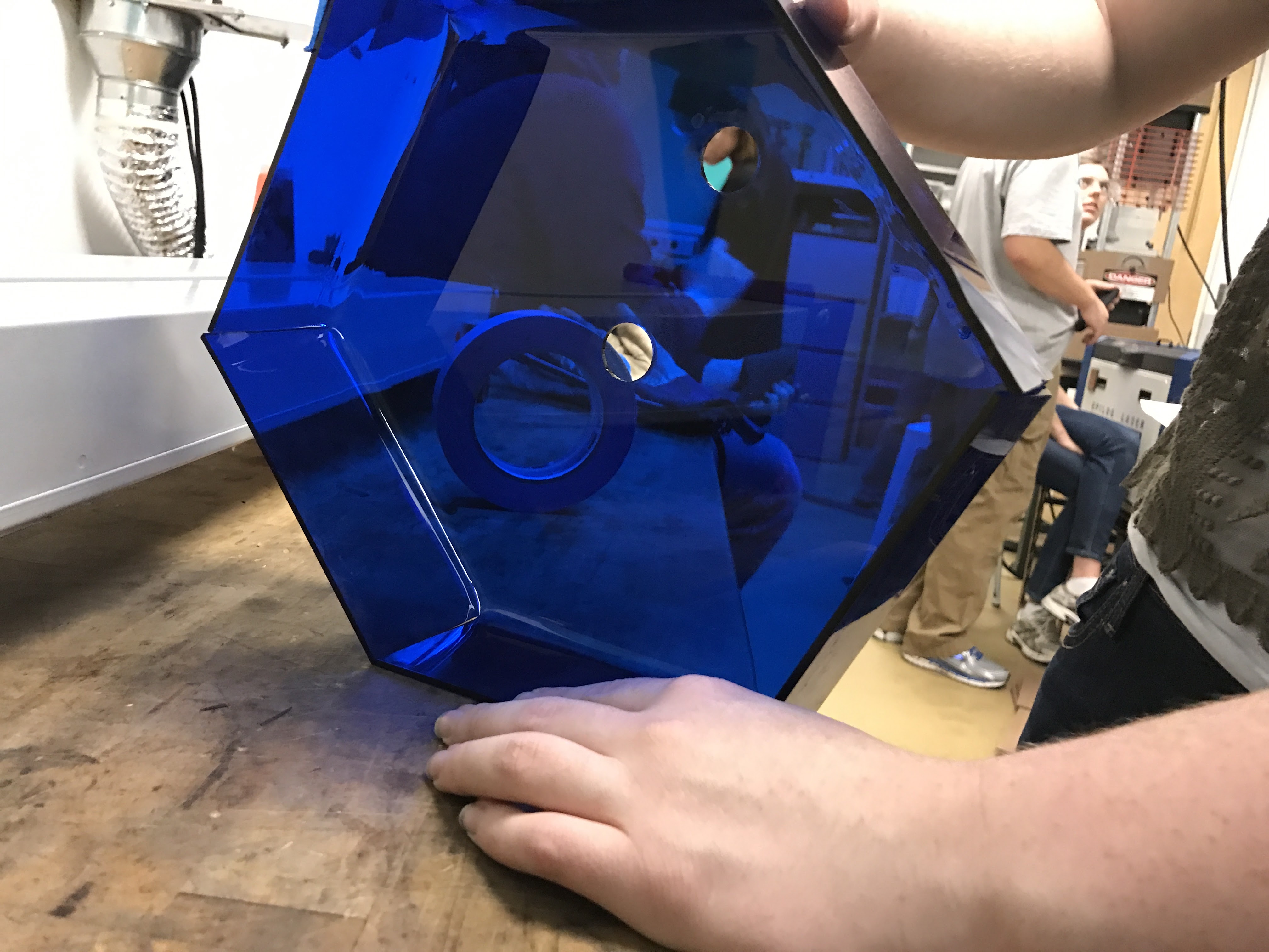
Laser Cutting in Action
It is difficult to create acryllic pieces to fit perfectly inside a 5-gallon bucket, so we designed the roller platform to be slightly smaller then neccessary. Then, we placed 4 bolts around the perimeter of the bucket, in order keep the platform level and at the proper height.
Drilling a hole in the bucket
Next, we created a funnel by cutting a smaller, 2-gallon bucket to be 3inches tall. This funnel has three holes in it, one for the pipe holding the lights, one for the mister, and one for the pipe that drains the water back into the water resevoir. The funnel is not attached to the plant level, but instead butts up against it. The funnel is supported by small legs fixed to the lower level. The funnel fully encompases all of the plant roots, and allows the system to remain fully watertight. We also created legs to attach the plants to the rotating ring gear, allowing them to rotate.
The final step was to connect all the tubing together and allow for water flow. We used fittings, hose clamps, and L-brackets to ensure that the tubing would remain attached and never kink. Caulk and acrylic glue were used to seal holes and create water tight connections. At this point we were ready to configure all the electrical components!