• Home
  • Mechanical
  • Electrical
  • Code
  • Our Story
    • Sprint 1
    • Sprint 2
    • Sprint 3
    • Sprint 4
  • Our Team

Sprint 4

The last push

12/14/2015

0 Comments

 
Hi all!

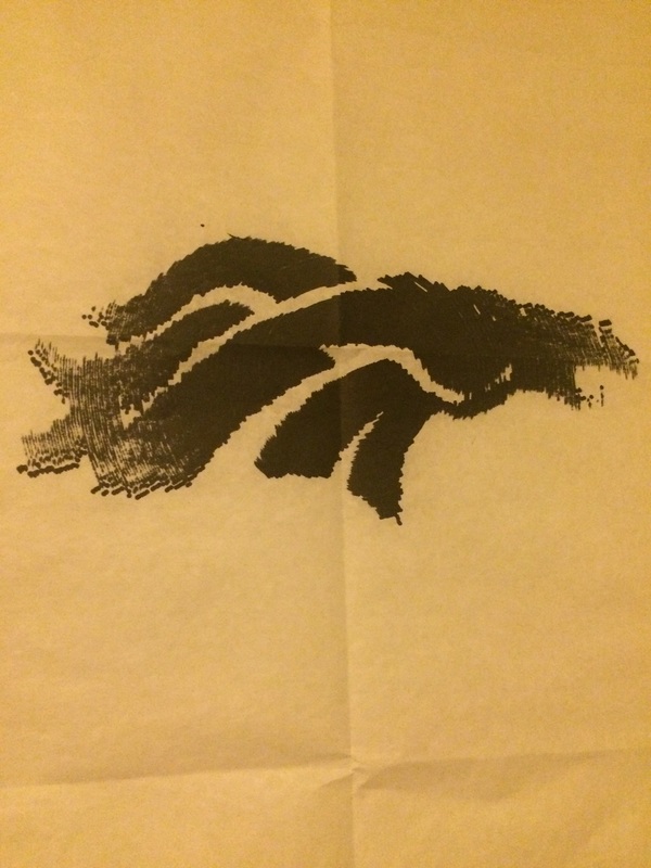
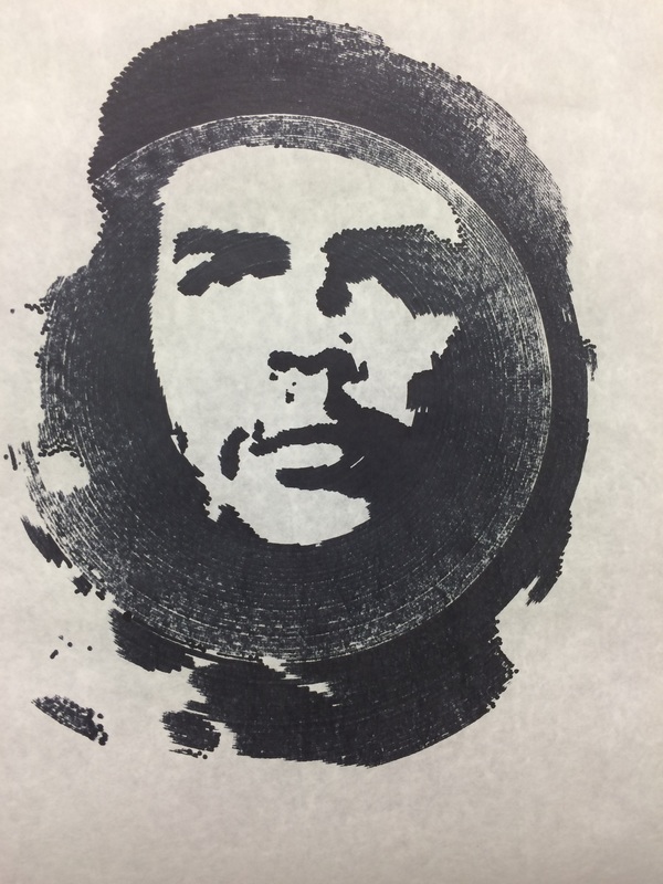
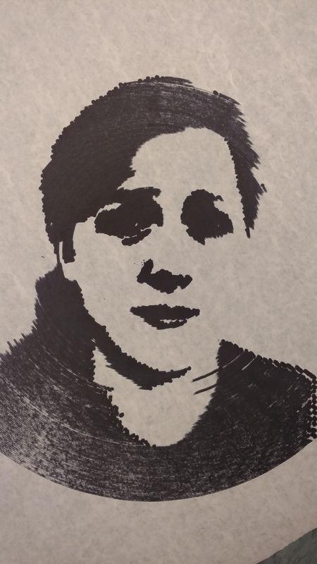
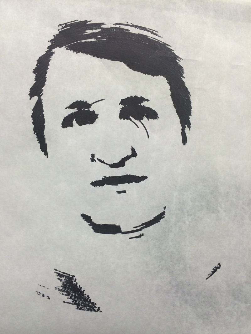
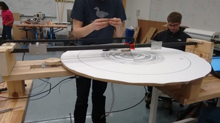
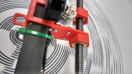
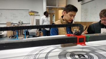
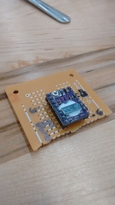
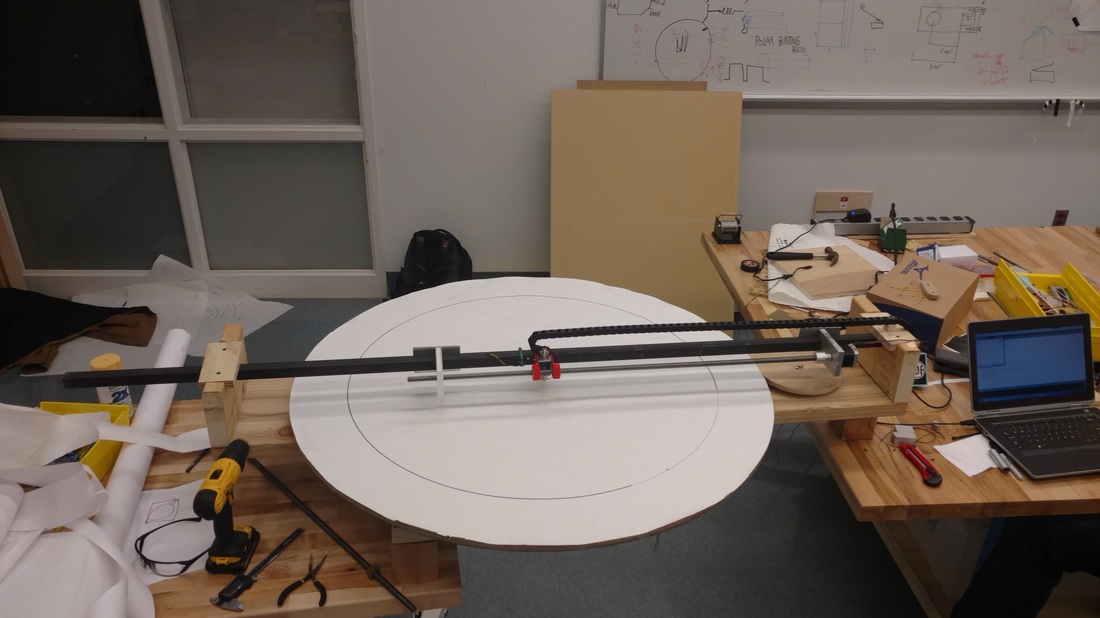
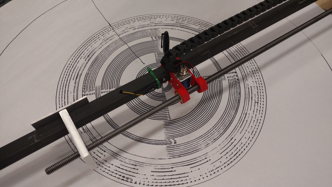
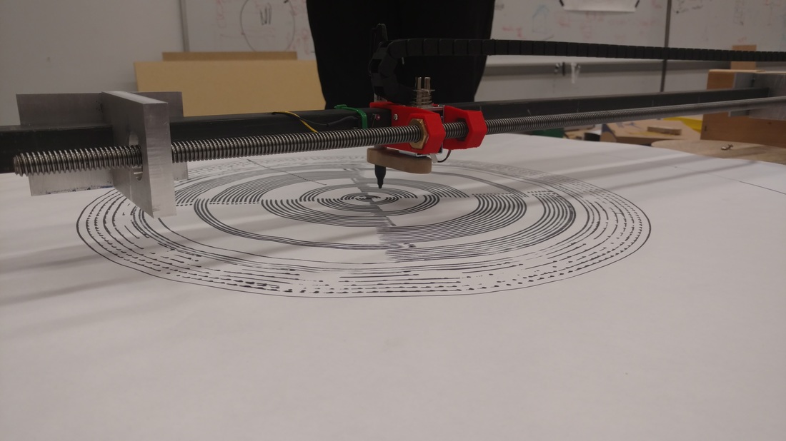
We've been a little busy recently to write blog posts, but we've been hard at work making the last push toward finishing our product in time for the end of classes. We've been hard at working cleaning up circuits, mounting pieces, and fixing code. And, the most exciting news of all: it draws! We've gotten our printing press to draw any arbitrary images that we feed it. You can see a few of our awesome images below. 
0 Comments

We have an image!

12/11/2015

0 Comments

 
After finally getting our mechanical and electrical systems running, we've been able to implement the code to make an image! This square is the first attempt to draw a completely non-circular image, and we're pretty proud! From here out, we'll be tweaking our circuit boards to be more robust, cleaning up any physical blemishes, and perfecting code to draw full portraits. 
0 Comments

Updates and changes!

12/9/2015

0 Comments


Frankie here, enjoy some explanations of recent design changes!
Bar base-
Rather than continuing with a full box/board as the base, we have now shifted to a less bulky design. The base is only a standing bar that goes under the plate, housing the electronics and providing the structure for the gantry above. This makes the whole thing lighter, less awkward to move and allows access to much more of the bottom of the plate, for use in position sensing.

Picture

Encoder and  Limit Switch Under-
Instead of placing the optical encoding ring and limit switch on the top or side of the plate, they are now underneath, creating a slicker design as they are out of sight and, a larger plate, as they don't take up any drawing space. Also they are now closer to the breadboard, for easier and cleaner wiring.

Picture
Picture

Little Wheel (Side Driver & Spring)-
A little sense was driven home the first time the plate was spun at full speed, and it became obvious the solenoids would not be able to keep up. Since then we have reduced the speed twice: first with the relocation of the driving motor to a smaller side wheel, and second with the 1/2 reduction of the side wheel. Though this has drastically improved our speed challenge, with the introduction of the side wheel came the some new problems, namely maintaining constant pressure/contact between the two. Quickly though, this issue too was resolved with the addition of a clever spring that pulls the side driver against the plate.

Picture
Picture
Pen Car-
The Pen Car has also been updated. Now a single printed part, with a spaces to stabilize the pen.
Picture
Wire Conduit-
The wires are now run using flexible plastic conduit, creating a cleaner look, and fewer points of tangling/vulnerability.
Picture

Proto Board-
We discovered that the breadboard is not rated for high enough current draw, so we are now using a smaller protoboard, also more permanent thought less easily iterated upon.

Picture
0 Comments

Pictures and Progress

12/8/2015

0 Comments

 
Picture
Picture
Picture
So far we've been able to construct a mechanical system that looks like a robust iteration of our MVP and get our limit switches, encoder, and solenoid to work together to draw alternating quarter circles. Now we can get clean, cool geometric patterns! Frankie's post details every specific choice made in this process, so I'll refer you there for a technical breakdown- this post shows our project's current drawing capabilities. 
​-Mackenzie 
0 Comments

Measuring wheel rotation

12/1/2015

0 Comments

 
During our sprint review, a professor suggested that we use an IR sensor to measure wheel rotation instead of our rotary encoder. We printed out a pattern and taped it to the wheel, set up the circuit, and programmed the Arduino to measure wheel rotation. We were very successful. The Arduino counted a rotation of the wheel with an error of only about 1 centimeter. We're going to use a limit switch to calibrate the Arduino and get rid of any additive error, so this is an acceptable amount of error. You can see our test below. 
0 Comments

Time to slow down

12/1/2015

0 Comments

 
Last night we prototyped a cardboard wheel in order to increase the speed of the platter and decrease the load on the motor. After testing the wheel, it was clear that we don't need to go any faster. The results of the test are below. As a result, we're going to go back to the MDF wheel and driving the wheel more slowly. 
0 Comments

    Archives

    December 2015

    Categories

    All

    RSS Feed

Create a free web site with Weebly
  • Home
  • Mechanical
  • Electrical
  • Code
  • Our Story
    • Sprint 1
    • Sprint 2
    • Sprint 3
    • Sprint 4
  • Our Team