• Home
  • Mechanical
  • Electrical
  • Code
  • Our Story
    • Sprint 1
    • Sprint 2
    • Sprint 3
    • Sprint 4
  • Our Team

Sprint 3

Sprint Done!

11/21/2015

 
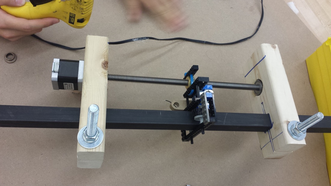
​   So as you can see, we put together our Sprint 3 deliverable. Unfortunately, our design pivot left us short on time to make our subsystems integrate prettily or make sure our motor could turn the new, heavier wheel. 
   What's really exciting is that we have all our subsystems independently working with proof that they can integrate. In the above video, you can see Kai hit the limit switch and start the stepper motor and solenoid's programmed drawing pattern. Although not visible in the video, we also have a rotary encoder that tracks rotation of the wheel, although we're still experiencing slippage.
   Our wheel is also now safer, tangle-free, and (supposedly) driven by our DC motor underneath with three guide wheels to provide support for the rotation. 
   In our next sprint, we're going to address potential risks in lack of precision, trouble integrating, messy wiring, lack of electrical power, parallel processing, and strength of motor. We want to minimize these risks by integrating early, finalizing our design quickly(no more pivots), keeping clean circuit hygiene, specifying our parts quickly, using interrupts in our code instead of delays, and potentially driving our wheel from the side or changing our wheel material. 
   We'll be buying parts over Thanksgiving break to try and eliminate wait time so we can start working ASAP. 

Til next time!
​-Mackenzie


So you want a giant spinning wheel?

11/19/2015

0 Comments

 
Well we have a giant spinning wheel. Here are the highlights from its construction:
  • Everything about the wheel was cnc: from the shop-botted mdf itself to the bracket that connects the axle of the motor to the wheel. This way, we know that nothing will be off center (something that could make this very unsafe at high speeds).
  • We are using three wheels embedded in the base to support the platter instead of a lazy susan because the wheels seem to do better at high speeds than the lazy susan bearing. 
  • The motor is strong enough to keep the wheel spinning for a little bit but isnt strong enough to get it up to speed. This means we need a bigger, better motor.
0 Comments

Step up

11/17/2015

0 Comments

 
​Today we worked on implementing the last bit of the hardware that we hadn’t done yet: the stepper motor drivers. We read that we should calibrate the maximum current that the driver could send by tuning a potentiometer. After a long time trying to calibrate this by measuring a reference voltage, we finally decided to hook up everything. After hooking up the power supply and running a bit of code to control the stepper motor, we realized that the motor wasn’t doing much and the driver was hot. We decided to swap out the driver and try to tune the potentiometer with the motor hooked up. By looking at the current on the power supply, we were able to tune the maximum current. We were able to edit code to control the motor. However, the driver still was quite hot. We need to seek the advice of the NINJAs or instructors whether this is normal. 
0 Comments

The hip, new gantry prototype

11/17/2015

0 Comments

 
Kai and I just finished up a gantry prototype that makes good use of the sturdy, steel guide bar. We have two wooden clamps that hold the lead screw parallel to the guide bar. Of note is the fact that this prototype will easily incorporate the longer lead screw that we have ordered from McMaster. Also the pen car we have right now is made out of legos which is a prototype that will easily transition into a single 3d printed part. The more we work on this project, the more important it is to prototype quickly, but prototype with future implementation in mind so that each step of fabrication can easily flow into the next. If all goes well, we might begin working on mounting the platter onto the motor tonight.
Picture
0 Comments

November 17th, 2015

11/17/2015

0 Comments

 
We have working solenoids! They took some time to wire up correctly, because we had to spec out some parts so we could supply enough power to them while controlling them from the arduino. Check our testing demo here:

We followed the circuit design shown in this tutorial, but used different parts with different specifications. The solenoids we got took 12V of power at 2.1A of current, and we were able to find some transistors that could handle up to 3A, with an emitter-base voltage rating of 5V (to match the 5V that our arduino put out). We found some diodes that would allow 3A of current through in one direction, and also prevent kickback voltage from the solenoids from damaging the rest of our parts. We calculated the base resistor value to satisfy the following expression: 

(V_base - V_drop) / R_base * Gain = C_collector.

That is, the current through the base (calculated by the base voltage minus the voltage drop over the base resistor) multiplied by the transistor's gain is equal to the collector current. The voltage drop and gain are both values that we found on the data sheet's figures, the collector current is our necessary 2.1A, and base voltage is the arduino's 5V.


Best,
​Kai
0 Comments

Refining our mechanical design

11/17/2015

0 Comments

 
We found a long bar of steel tube in the mech-e stockroom last night that would make an excellent guide bar for our pen car. With that in mind, I drew up some quick detail sketches of what our mechanical system could end up looking like on my way to breakfast. Check it out:
Picture
0 Comments

Making it bigger

11/16/2015

0 Comments

 
We have decided it is time to move toward a full scale prototype. Four foot diameter posters sounds like a really sweet idea, so we are planning on going to Home Depot tomorrow morning to grab some plywood and then shop-bot out the "platter" that holds the paper beneath the pens. It is more than likely that the motor we are using right now is under powered for a four-foot platter, so a scavenged motor might be in our future as well.  
0 Comments

Time to encode the turn of the wheel

11/12/2015

0 Comments

 
Hey guys, it's Sawyer again, 
​
Today we learned about using the rotary encoder. For the final product, we're going to be using the rotary encoder to sense the rotational position of the wheel. We found a circuit diagram and Arduino code below. It turns out that there is a ground pin on the encoder and two signal pins. The two signal pins change from high to low when the encoder rotates. If pin B is high when pin A drops, the encoder is turning clockwise. If pin B is low when pin A drops, the encoder is turning counter-clockwise. The Arduino can count these drops and calculate how far the encoder has rotated. We wrote some example code that counts these rotations and lights up an LED so that you can turn the encoder to turn up or down the LED's brightness. The next step is to attach a wheel or gear to the encoder and place it on the edge of the wheel, so it measures the wheel's movement along its edge.
0 Comments

Questions Answered?

11/10/2015

0 Comments


​Frankie again.... back at ya... seconds later.

How do we move the pens?
One option: Record player!
          Benefits- would look fricken awesome, have a baler interaction and minimally impact codding complexity. 
        Drawbacks- hard to control the wibbly wobbly  nature of a thee foot long arm with rapidly vibrating at the end of it. Also small changes at the servo, would represent large changes at the pen end, which would fight us in our never ending expedition for resolution.
Another option: Gantry!
             Benefits- would solve the stability issues, as well as the resolution problem, allows us to reuse many of the mechanisms we developed pre-pivot
              Drawbacks- Doesn't look like a record player...
SO I think we are going with the Gantry....

How do we scale to lots of pens?
So it turns out it this is pretty simple... if we have the lead screw extend past, the center on one side, and the  edge of the spinning paper on the other, we can have many pens stacked next to each other.
0 Comments

PIVOT!!!!

11/10/2015

0 Comments

 
YO IT"S FRANKIE,
First day of Sprint 3 and we have completely rewritten our design. Rather than rotating the pens, pen-cars, lead screws and servos, which presents us with weight distribution problems, and the greater issue of spinning wires, we have decided to rotate the paper, on a Lazy-Susan, like on a record player.
This eliminates many of our design problems, but presents some new questions. How do we move the pens, how does this scale to multiple pens?
​
Picture
0 Comments
<<Previous

    Archives

    November 2015

    Categories

    All

    RSS Feed

Create a free web site with Weebly
  • Home
  • Mechanical
  • Electrical
  • Code
  • Our Story
    • Sprint 1
    • Sprint 2
    • Sprint 3
    • Sprint 4
  • Our Team