Electrical Subsystem
The electrical system consists of a variety of sensors and actuators that the Arduino controls. It can be broken down into several sub-circuits, including the solenoid circuit, IR sensor circuit, and limit switches (image directly below), and the stepper driver (second image below).
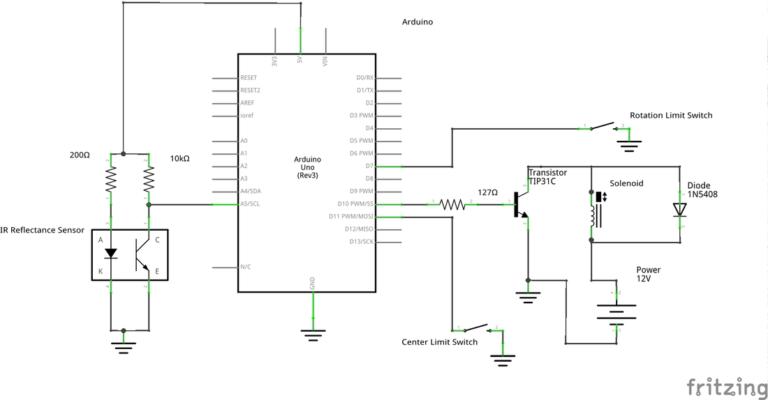
This circuit diagram shows several of the electrical components wired to the Arduino.
The limit switches are wired very simply, going from the digital input through the switch to ground.
The IR Reflectance Sensor circuit is adapted from a similar circuit used in a line-following robot lab. The data sheet shows that the LED has a voltage drop of 1V regardless of current. This means the current from a 200Ω resistor and LED is 20mA. At a very close proximity and using a mirror as a reflective surface, the current is about 2mA for the collector. In these optimal conditions, a resistor value of 2.2KΩ is ideal. Because our sensor is not operating in the same ideal conditions, we increased the value of the resistor to 10KΩ.
The solenoid is more complicated and adapted from these instructions, but used different parts with different specifications. Our take 12V of power at 2.1A of current, and we use a transistor that can handle up to 3A, with an emitter-base voltage rating of 5V (to match the 5V that our arduino put out). We use a diode that will allow 3A of current through in one direction, and also prevent kickback voltage from the solenoid from damaging the rest of our parts. We calculate the base resistor value to satisfy the following expression, to find that 127Ω will work:
(V_base - V_drop) / R_base * Gain = C_collector.
The power supply gives 12V, 8A, which is over-spec'd for the components that we use. Both the solenoid circuit and the stepper motor (below) draw from it.
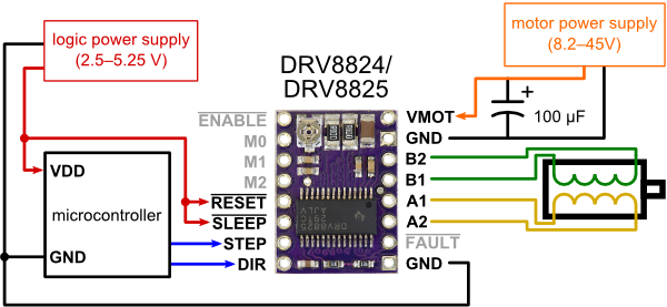
Our stepper circuit is designed exactly as instructed for the stepper driver that we are using. The motor power supply is the same one that powers the solenoid, and the logic power supply is the Arduino. The ENABLE pin goes to pin 6 in the Arduino, STEP to pin 5 and DIR to pin 4.
The final electrical component is the DC motor that driver the platter, and is as simple as wiring up a 12V, 2A power supply to the motor.