
DotBot Subsystems
What went into the DotBot, and how did we make it? Click the images to learn more about each subsystem.
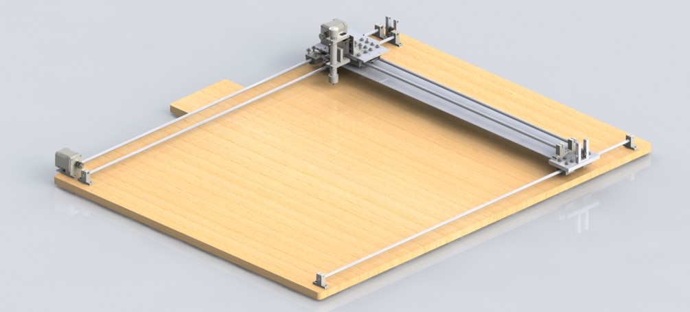
Our full mechanical system is a 2’ x 3’ 3-axis gantry structure. The X and Y axes of the DotBot move along steel rods using a stepper-powered pulley system, while the Z-axis is controlled by a solenoid motor. Fabricated parts were CADed in Solidworks, 3D printed, then machined. Click the image to the right to learn more about this subsystem.
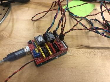
Our full electrical system connects our two stepper motors and one solenoid motor to our Arduino Uno board through a CNC motor sheild, which is connected to a power source. Click the image to the right to learn more about this subsystem.
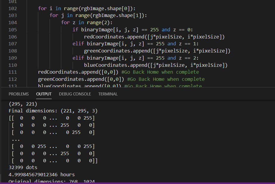
Our full software system consists of code written in Python and in the Arduino language. The Python code handles image processing through a dithering algorithm, coordinate packaging, and sending off the coordinates to the Arduino microcontroller. The Arduino code requests coordinates over Serial communication and directs the motors to the corresponding positions. Click the image to the right to learn more about this subsystem.