
Software Subsystem
A look into the code that runs the DotBot.
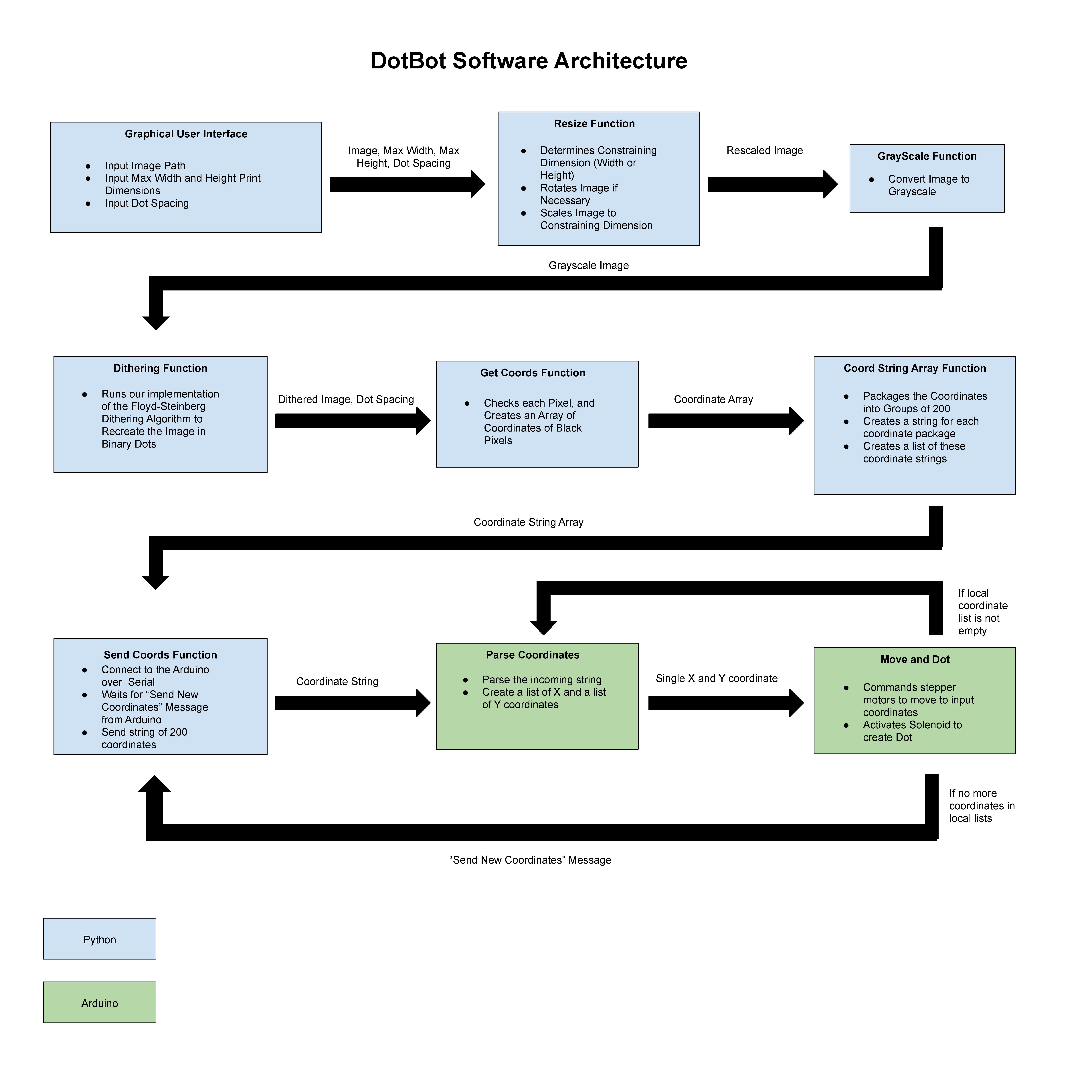
Image Pre-Processing:
In order to prepare the image for dithering we first must resize it. We first take in the image, max printing width and height parameters, and the dot spacing. With that information, the resize image function uses OpenCV and Numpy to flip and scale the image as necessary in order to make it as close to the max dimensions as possible, while maintaining the aspect ratio.
Dithering:
In order to convert the image to dots we used a method called dithering. Specifically we used the Floyd-Steinberg Dithering Algorithm. The way the algorithm works is by going pixel by pixel from the top left corner all the way down to the bottom right corner rounding the grayscale pixel value to either 0 (black) or 255 (white). However, the error from this rounding is spread to the surrounding pixels, increasing their pixel values. 7/16ths of the error is added to the pixel directly to the right of the current pixel, 1/16th of the error goes to the pixel one down and to the right, 5/16ths of the error is added to the pixel directly below, and 3/16ths of the error is distributed to the pixel down one and to the left. As you may notice, the total error distribution adds up to 1, meaning the entire error is distributed across the image. Check it out live in the GIF above!
Sending Coordinates:
Once the image is dithered, we run through the pixel matrix and create a list of X and Y coordinates corresponding to each black pixel. Then we package the black coordinates into groups of 200. Then these packages are sent over serial as strings to the Arduino. Packaging the coordinates into groups of 200 minimizes the amount of serial messages needed to be sent between the Arduino and Python scripts.
Parsing and Dotting:
The Arduino sends a message over serial requesting coordinates from python. Once the coordinates are received, the string is parsed two lists are made, one with X coordinates, and the other with Y coordinates. The Arduino then iterates through these lists, pulling a single set of coordinates at a time. The X and Y stepper motors are then commanded to move the pen to the next coordinate, based on the current position. Once the pen has reached the given coordinates, the solenoid is activated, creating the dot.
Other Features:
- Calibrates on start up, moving to 0,0 and setting its current position to 0,0
- If a limit switch is activated during print, code breaks
- Graphical user interface allows smoother loading, visualizing, and printing of images
- Once the last coordinate is reached, code breaks