
Sprints
Follow our progress through four 1-2 week sprints.
Sprint 1
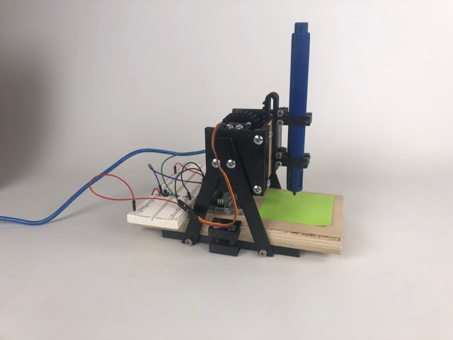
Goal: Our Sprint 1 deliverable was a 1-axis prototype that could consistently draw a dot in place. By the end of the sprint, our servo-driven rack and pinion mechanism moved a pen up and down to dot a post-it note at a continuous rate.Mechanical: We designed and 3D printed a pen holder, a rack and pinion, and a base assembly.
Electrical: We wired a simple circuit that connected our servo motor with the Arduino.
Software: We coded a short program that had the servo motor turn the pen down and back up at the push of a button.
Conclusions: We decided to pivot away from the rack and pinion because 3D printing gears is a pain, and the current design we went with had some flaws, mainly the rack tilting and speed of dotting. With that in mind, we made the move to replace the borrowed servo motor with a purchased solenoid and will adjust the mechanism to suit it.
Sprint 2
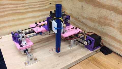
Goal: Our Sprint 2 deliverable was a 3-axis prototype that drew dot pictures using preloaded path files. By the end of the sprint, we had a working, albeit quite small, machine that was able to both draw and dot a preloaded spiral on a sticky note.Mechanical: We designed and prototyped the X and Y axis of the DotBot, including mounts and placements for the stepper motors, a pulley system for each axis, linear actuation mechanisms, and power transmission from the timing belts.
Electrical: We figured out power source conversion, ordered and implemented our stepper driver shield, installed limit switches, created new circuits between all three motors and the Arduino, and began testing a PCB protoboard to use with the solenoid motor.
Software: We loaded GRBL firmware onto the Arduino, used a Universal GCode Sender GUI to control our X and Y stepper motors, and wrote Arduino code to control the dotting solenoid motor.
Conclusions: Because the GRBL firmware was comprised of previously-existing code, we decided it would be more conducive to our learning to write the image processing and path creating code ourselves. Thus, we planned a software pivot, did some of our own research into image processing software, and decided to move forward with the implementation of a dithering algorithm instead of GRBL.
Sprint 3
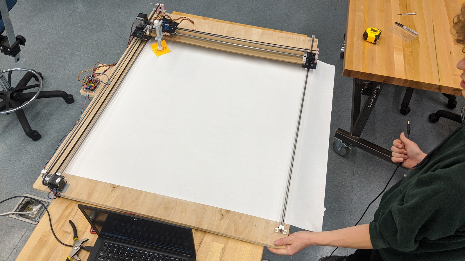
Goal: Our Sprint 3 deliverable was a full-size, 3-axis prototype that drew pictures using image processing. By the end of our sprint, we had an operational 2’x3’ gantry that could draw a large dot picture given an image, through the implementation of a dithering algorithm.Mechanical: We redesigned our gantry plates, removed interference to the timing belts, replaced our aluminum rods with steel, created part drawings to mill, created a sheet metal plate to connect motor platforms on the Y axis, and replaced our base plate, pen holder, and pen-to-solenoid holder with new parts.
Electrical: We updated and reintegrated our solenoid-to-Arduino circuit and continued wire-management work.
Software: We implemented stepper movement without the use of GRBL, integrated the Floyd-Steinberg Dithering algorithm, implemented Serial communication between our image processing python code and our Arduino code, packaged our coordinates in arrays to speed up this communication, and coded in image resizing, orientation, and dot density.
Conclusions: This sprint, we accomplished our MVP. However, we realized we wouldn't have the time to include some stretch goals we had dreamed up, such as a color-switching utility. We sadly bid those pipe dreams farewell, and decided to spend our last efforts cleaning up both hardware and software.
Sprint 4
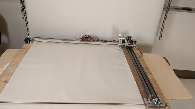
Goal: Our Sprint 4 deliverable was a fully-machined version of our completed prototype. By the end of our sprint, we had replaced all 3D printed parts on the DotBot with parts we machined.Mechanical: We milled all pen holder parts, timing belt holders, and all the gantry platforms.
Electrical: We replaced our solenoid, which stopped working midway through our final sprint.
Software: We cleaned up all our already-existing code and finalized our website documentation of the project. We began implementation of a GUI and fixed the resizing function.
Conclusions: The weight of the aluminum is compressing the spring on the solenoid and since the board is plywood, it was sanded but never faced. In the future we'd like to replace the base with faced MDF and swap out the spring to reduce the pen dragging on the paper during a print.