
Electrical Subsystem
A look into the circuit design of the DotBot.
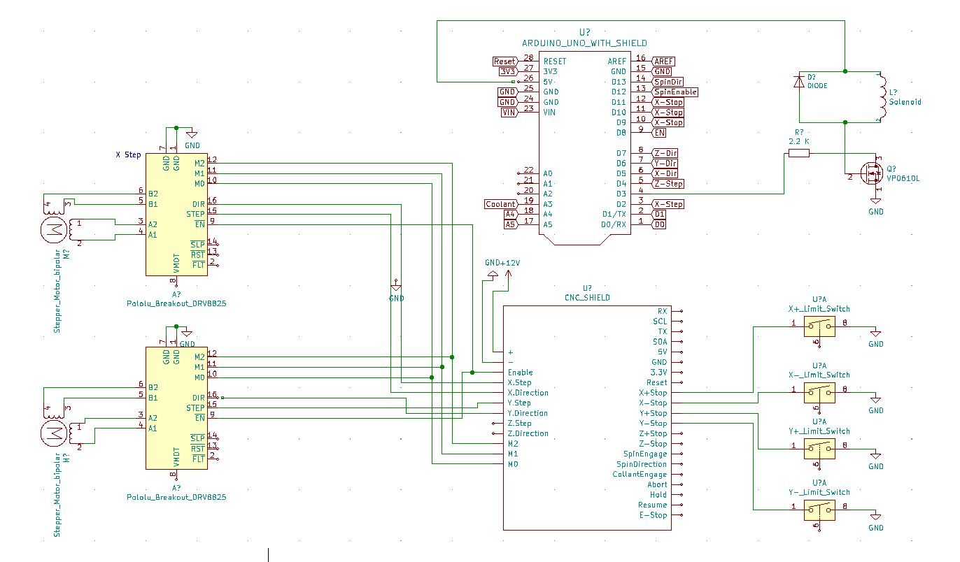
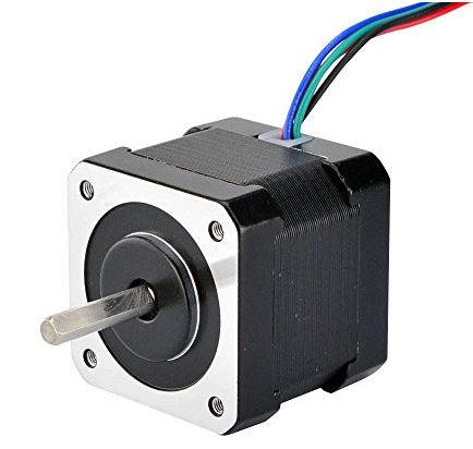
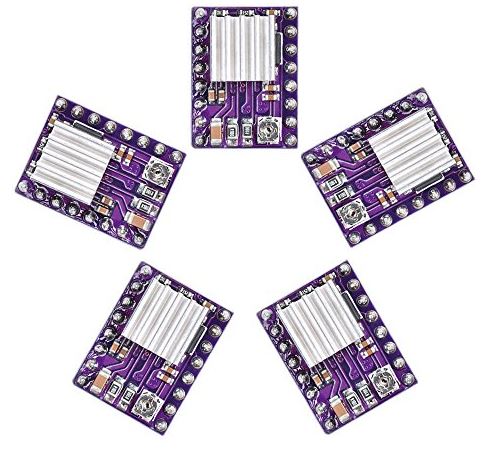
For the electrical aspect of DotBot, we wanted to keep a straightforward and streamlined design, strictly following the K.I.S.S. principle. Our main drive and focus was on function. The two key functions for the DotBot were a precise movement of the gantry and a linear actuation to make the dot. To move the gantry in a quick and precise fashion, we chose to use Nema 17 2A stepper motors driven by DRV8825 stepper motor drivers. For ease of management and integration with the Arduino, we additionally chose to purchase a CNC shield. To actuate the pen holder we chose to use a 12V 10mm throw solenoid.

While testing the solenoid, we discovered that underpowering the solenoid with a lower voltage was actually to our advantage. This is due to the fact that at higher voltages the solenoid was being actuated with too much force and it caused severe shaking in the assembly. Additionally, at higher voltages the pen was being pressed too hard into the paper and we were wasting ink. For these reasons, and in order to lower the number of components needed to make the system operational, we powered the solenoid through the 5V pin on the CNC shield.
To power the solenoid, we utilized an N channel MOSFET transistor, using a digital output signal from the Arduino to actuate the system. We used a flyback diode to prevent voltage spikes when power to the solenoid was interrupted while moving to the next dot location.