Mechanical
Robot Body
|
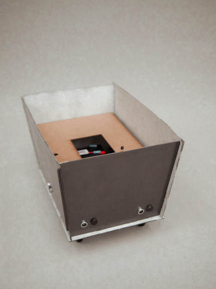
The final mechanical design consisted of a 14” x 10” x 9” trapezoidal box that was the body of the cart. This housed all the electronics under what we called the false bottom. This false bottom was a panel we inserted into the body of the robot to protect electrical components as well as improve the overall look. We also had the wheels mounted under the body of the robot, giving it a much sleeker look and stabler assembly than our original plan of having them on the sides. Of hardboard and metallic spray paint, our final design also incorporated a conscious effort to improve aesthetics.
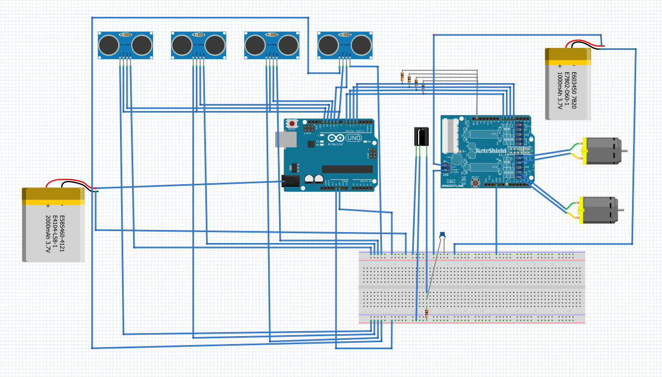
We used a 12 volt lead acid battery to power the motors. We chose this because we wanted to make the chassis rechargeable with by adding a plug. We also added switch within the circuit with the battery as it would open and close the current going toward the Arduino to turn it off and on. New wheels were purchased for better traction and to look better overall than the wheels that we made (3D printed). There are 4 ultrasonic sensors, two on the front and one on each side, which would allow the robot to adjust itself it the user takes a sudden turn. There will also be an IR receiver in the front to trigger the ultrasonic sensors. |
Wheel Mounts
|
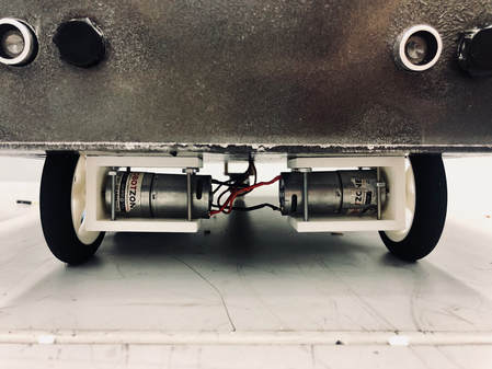
The wheel supports that we had before were not ideal for the motors that we had. The main problem that occured was that over time the wires began to cross in the support and that cause the motors to not work when they were called in the code. This was due to the supports being loose and that cause the motors to spin as the wheels were moving. Our new motor mount was made specifically to fit the motors snugly as it has screw holes in the from next to the shaft. The support would connect to the chassis and the motor, supporting in much better than before and has less potential to cross wires.
|
Beacon
|
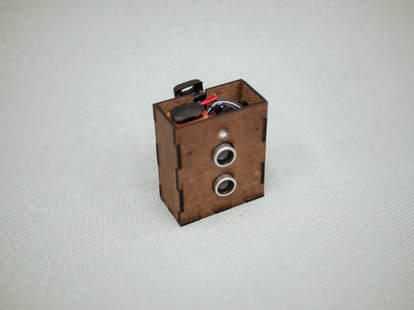
The final mechanical design for the beacon, which will be clipped onto the user’s back pocket so that the ultrasonic sender is pointed at the receivers on the robots, is a 2” x 1” x 2.5” box of hardboard. Inside, this will house all the electrical components needed to have a functioning beacon. This includes a 9V battery, and battery snaps to connect to the battery, which enables it to be easily switched if it runs out, the Arduino nano, the ultrasonic sensor, and the IR sender. For aesthetic reasons, we were able to include this all in a relatively small, well-packed box. On the back is a clip that we screwed on that would easily attach onto someone’s back pocket.
|
Electrical
|
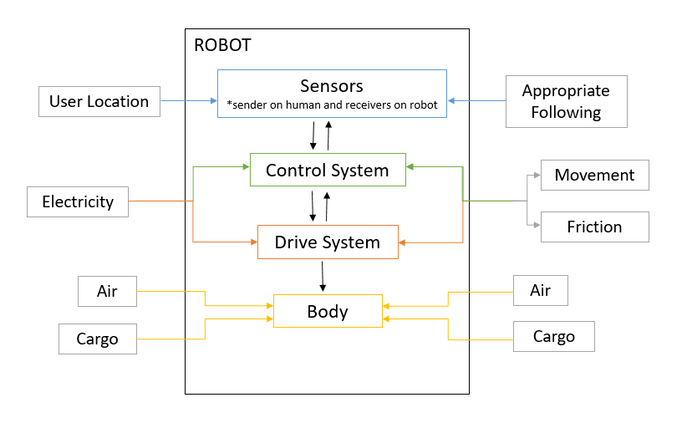
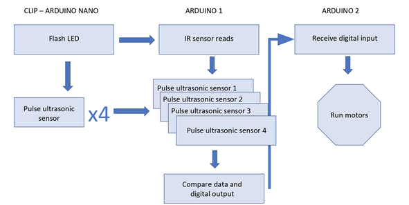
The final electrical system used a combination of infrared and ultrasound. The infrared sender on the beacon sends a signal to the infrared receiver on the robot. Because of the nature of light, this happens almost instantaneously and when the IR is triggered, it triggers the ultrasonics sensors, resulting in aligned ultrasonic sending and receiving.The ultrasonic sensor on the beacon are both sending signals, and the ultrasonic sensors on the robot are receiving. Each ultrasonic sensor is built to both send and receive, so as to ensure that the sensors on the robot only receive the signal from the sent the beacon (and not their own signal sent), we covered the sender on the robot sensors. Based on the readouts, we send commands to the motors to turn the cart towards the beacon, creating an effective follower.
|
Beacon
Software
|
For our final design we are using two Arduinos. This is due to some connectivity problems once we connected the motors. We have addressed the resulting unexpected sensor values by separating the motors and the sensors on different arduinos. These two are now only connected across two digital pins that send or recieve a high or low signal to communicate. The overall structure of the code has been developed. Most notably by splitting it up across the two arduinos. Now the arduino connected to the motors uses values of high or low that it receives from the other microcontroller to decide which way to turn the robot. The arduino connected to the ultrasonic and IR sensors is still pairing pulses with the arduino nano on the clip. It now outputs comparisons of distance information through the digital pins.
|
