Mechanical
|
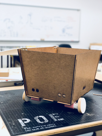
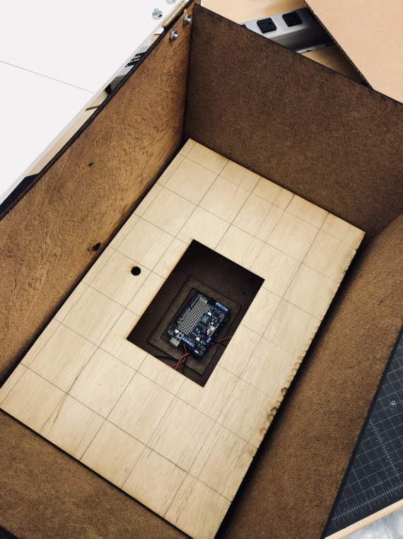
In Sprint 2, we decided to start shooting for the full MVP. We switched from cardboard to hardboard, bought and set up 12V DC gear motors, 3D printed some motor mounts to attach the motors to the bottom of the robot, 3D printed our own wheels to get the size and fit we wanted, and created an actual chassis. We CAD-ed and fabricated a more complex baseboard that had holes for wires and for connecting the walls of the robot, slanted walls that slotted together and into the baseboard and had holes for the sensors we planned to use, and a false bottom so that the electronics could rest inside on the baseboard and have the false bottom above them. This was so any items that are put in the cart won’t squash the electronics. We also added a hinged lid that was made of foam core, a lighter material, that we made designs for such that it could be automatically opened by the robot.
|
|
|
Clip Mount for Beacon
|
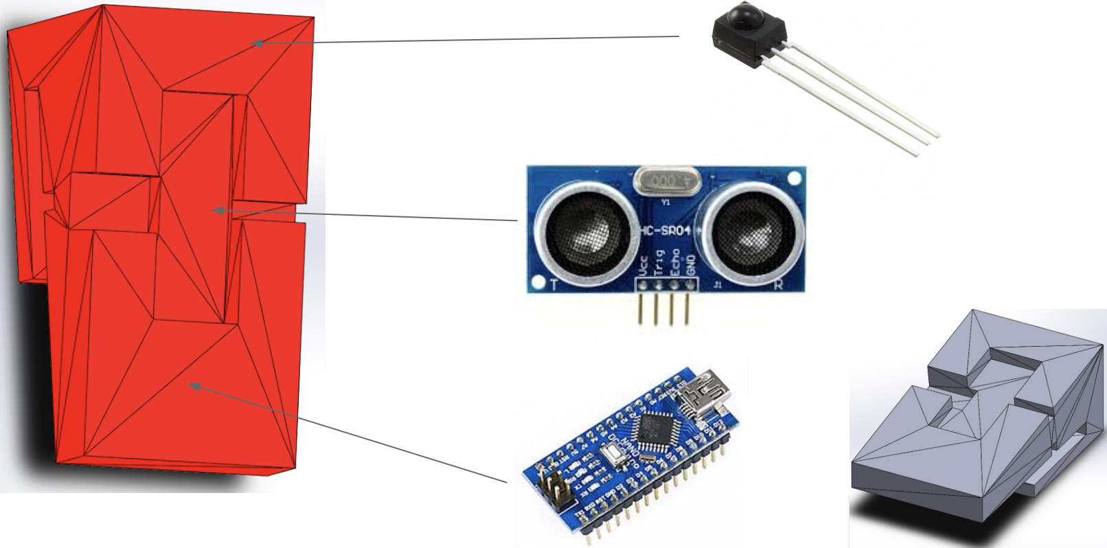
We also began working on the clip mount for the beacon that would contain the ultrasound sensors responsible for sending the signal, the infrared sender, and an Arduino Nano. One thing we forgot in this preliminary CAD design was a spot to put the battery in, which is something we took care of in the next sprint. Theoretically this clip would fit snugly into a person’s back pocket so that the send. That is the reason why the clip is slightly angled, so that the sender could be aimed towards the sensors on the robot.
|
ElectricalIn Sprint 2, we experimented with bluetooth communication to locate a beacon on a person. We tried to make and HC-05 (Arduino bluetooth module) tracking system. Unfortunately, this failed miserably. Bluetooth was nowhere near accurate enough for the setup and space we were attempting. We needed 3 HC-05 bluetooth modules for triangulation, which needed accuray in the centimeters, not only could we not get reliable communication, but the accuracy was in the decimeter to meter range. Better motor powering circuits were designed.
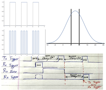
Therefore, we decided to make the beacon and following system from IR and ultrasonic sensors. Ultrasonic sensors were used for location, IR emitter and sensor were used to sync the 2 arduinos so that the ultrasonic sensors pulsed at the exact same time to ensure accurate distance readings. |
|
Software
For the second sprint we transitioned from using the microbits to ultrasonic sensors and a set of a paired infrared (IR) sensor and light emitting diode (LED). We incorporated two arduinos, one for the clip to be followed and one for the robot. The arduino on the clip is coded to pulse the ultrasonic sensor at at set timing. The IR sensors between the clip and the robot are paired to sync the timing of the ultrasonic sensors. The code on the arduino on the robot matches exactly the timing of the arduino on the clip through the paired IR sensor. The arduino on the robot rotates through pulsing the ultrasonic sensors after receiving a signal from the IR sensor. Once four data values have been received from the clip, the code goes through a slightly updated version of the algorithm that controls the motors by comparing the distances received by the sensors to their placement on the body of the robot.
Kaizen
We want to make sure to plan things better and get items ordered earlier so that we can start integration earlier as it is usually the most time consuming.