
Hardware
For a majority of the testing and designing process, we had to hold the string in our hands to feed it into the string dispenser. In order to keep the string art machine running for a long time, we wanted to design a spool holder. We 3D-printed a spool holder that replaced the part of the string dispenser that contained the bearings.
The spool holder had a horizontal tube that went through the hole of the coiled string. This design was inspired by a 90 degree tilted sewing machine construction. Regarding our first spool holder design, we ran into the issue that the string did not unroll as expected. We solved this issue with two solutions.
Since the spool was located right above the string dispenser, the angle that the string made with the spool holder was too steep. The steep angle created friction at the top of the string dispenser that required higher torque from the theta motor, which it couldn’t provide. To fix the issue of high friction at the string dispenser, we offset the spool holder to the side so that the string could be pulled tangentially through the string dispenser tube. For bigger string spools, we designed a piece that we could attach to the spool holder to counterweight the spool’s weight.
Furthermore, we realized that the original spool that we bought was weirdly wrapped. It was wrapped in a way that created even steeper angles with the string dispenser. We had to unwrap the string from the original spool and curl it onto a modified PVC tube. We laser cut MDF-disks to stop the string from falling off at the edge of the PVC tube.
After these two improvements, the string unrolled properly and we were able to run the string art machine for a long time without having to hold the string.
Software
For our final sprint, we made significant modifications to our software workflow (reference diagrams below).
We went from this:
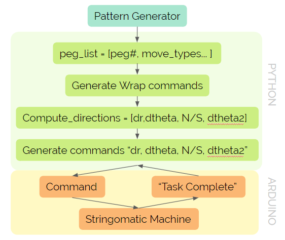
To this:
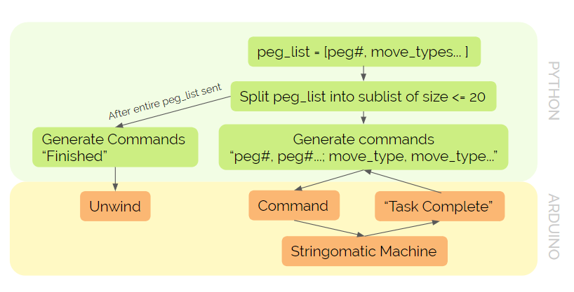
Instead of having python send individual peg coordinates to the Arduino, we moved all of the computation to Arduino. Currently, our python code directly sends the peg_list of tuples containing peg numbers and move_types through serial port communication. The Arduino script receives the peg_list in the form of a string, splits it into two separate lists (one for peg numbers and one for move_types), generates motor commands for each peg number and move_type, and executes the commands. While testing a large peg_list, we discovered that Arduino can only read in a string containing information for 20 pegs. As a result, we adapted our python code to split the peg list into subsets of 20. After a subset is sent via serial port communication, the python send_list_and_receive_response() function will wait for a “Task Completed!” message from the Arduino before sending the next subset. This change allowed us to drastically reduce the time spent on serial port communication.
Moving the computation into Arduino allowed us to make it more concise and logical. Instead of having the dispenser start right in front of the pegs, we offset the positions of each peg by half the distance between two pegs so that the midpoint between each peg is regarded as the real target position. In general, shifting our coordinate system by half a step enables us to reduce the computational complexity in our Arduino code. We now start between pegs 0 and 1.
We also modified the starting position of our system. Instead of having the radius axis move to the center after hitting the limit switch, it now moves 10 mm inwards, starting at the outer edge of the pegboard. This allows the Stringomatic to immediately start wrapping pegs instead of having to spend time moving to the edge.
Some of the most significant changes that we were able to complete after adjusting our code structure involve optimizing the wrap feature and adding an unwind function. In sprint 3, we accounted for the possibility of undoing a wrap when transitioning from a move_type of 1 to 0 by implementing a double wrap function. However, double wrapping decreased the efficiency of our system and was a nightmare to unwind. When we moved the computations to Arduino, we were able to separate the different move_types earlier on and make the wrap commands more versatile so the string dispenser can wrap around in both directions without undoing the previous wrap. We also attempted to make the wrap string movements more smooth, but quickly discovered that the stepper motors can only move in discrete steps, making it exceedingly difficult to get the motors to move around in a circular motion. We then tried to combine the five motor commands into a single command followed by two pairs with the motors in each pair running concurrently. However, the speeds of the two motors were difficult to put in sync and sometimes completely failed at wrapping around the correct peg. As a result, we decided to keep the five motor commands separate and just increased the speeds of the motors within the wrapAround() function.
The unwind function basically stores the opposite of each motor command into a stack. When python sends the “Finished” message, then the Arduino script will initiate the unwind process, which involves popping commands from the stack and executing them until the stack is empty. The unwind function was very convenient when we ran countless tests.
Since we did a lot of testing during sprint 4, we were able to optimize the speeds for our stepper motors. We found that the theta motor works the best when its speed is 0.8 revolutions per second. The radius motor has an optimal speed of 150 mms per second. During the wrap around command, the theta motor speed is increased to 2 revolutions per second, and the radius motor speed is increased to 200 mms per second.
Lastly, while testing we were able to detect a pretty significant bug in our computations. When deciding whether to use the radius axis to cross the board, we did not compare the correct theta values. Instead of comparing the differences between the desired peg location, the desired peg location - 360, the current peg location, and the current peg location - 180 (going across the board) and choosing to execute the path with the minimum difference, we compute the four possible paths by finding the difference between the desired peg location and current peg location and the difference between the desired peg location and the current peg location - 180 and then find the theta values to get to the same position but in the opposite direction. (360 - abs(diff)) * sign(diff). If both paths associated with the current peg location are less than 90 degrees, then the radius axis is not used to move to the next peg. Else, we would cross the pegboard and move the minimum theta value associated with current peg location - 180.
We tested our changes on both the 48 and 96 pegboards, and everything ran smoothly for shorter peg lists. Next, we hope to test our system with larger peg lists for demo day.
Check out our Project Overview for more info on the final product!