
Team Adryft finished the last sprint with a rotating peg board, functional image-processing code, and working Arduino controls. Let's see what they accomplish this sprint...
Hardware
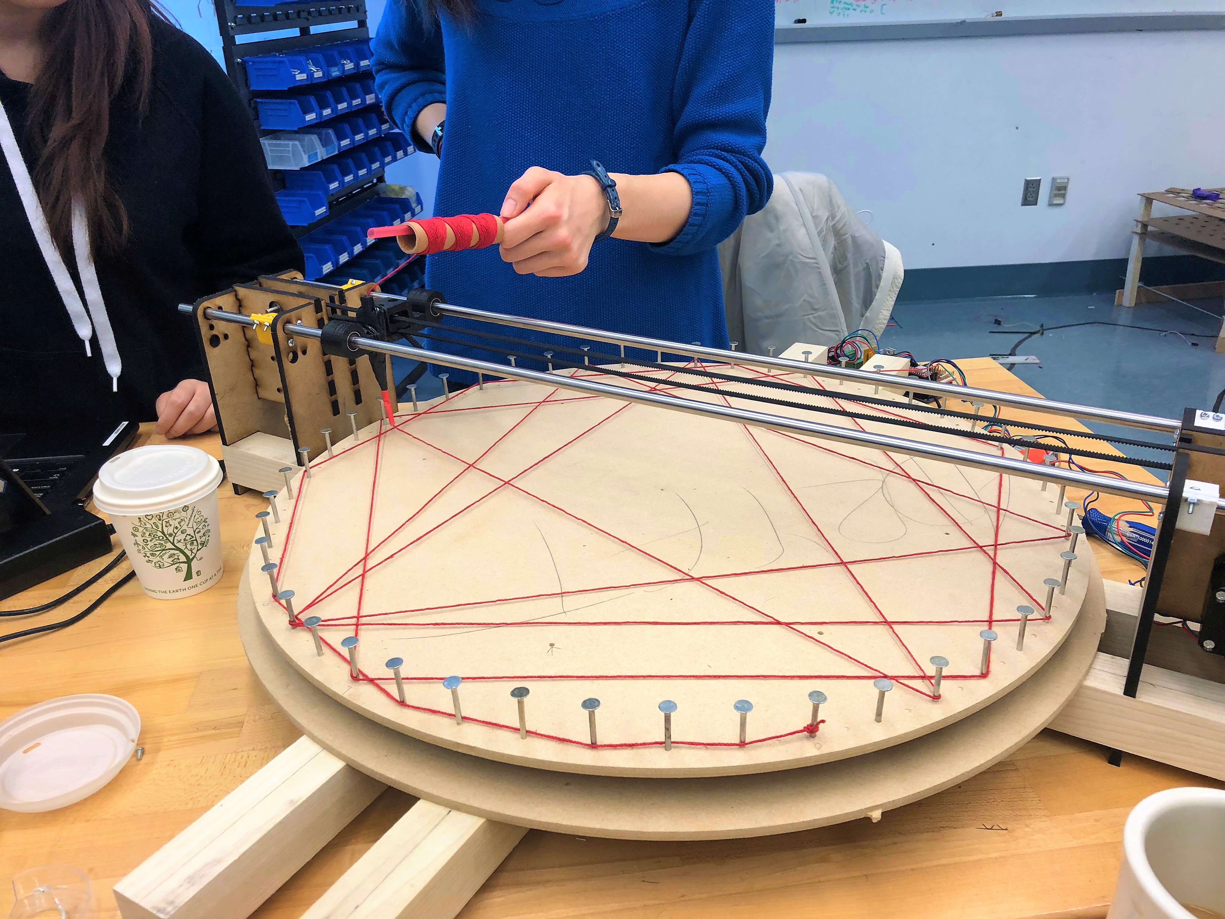
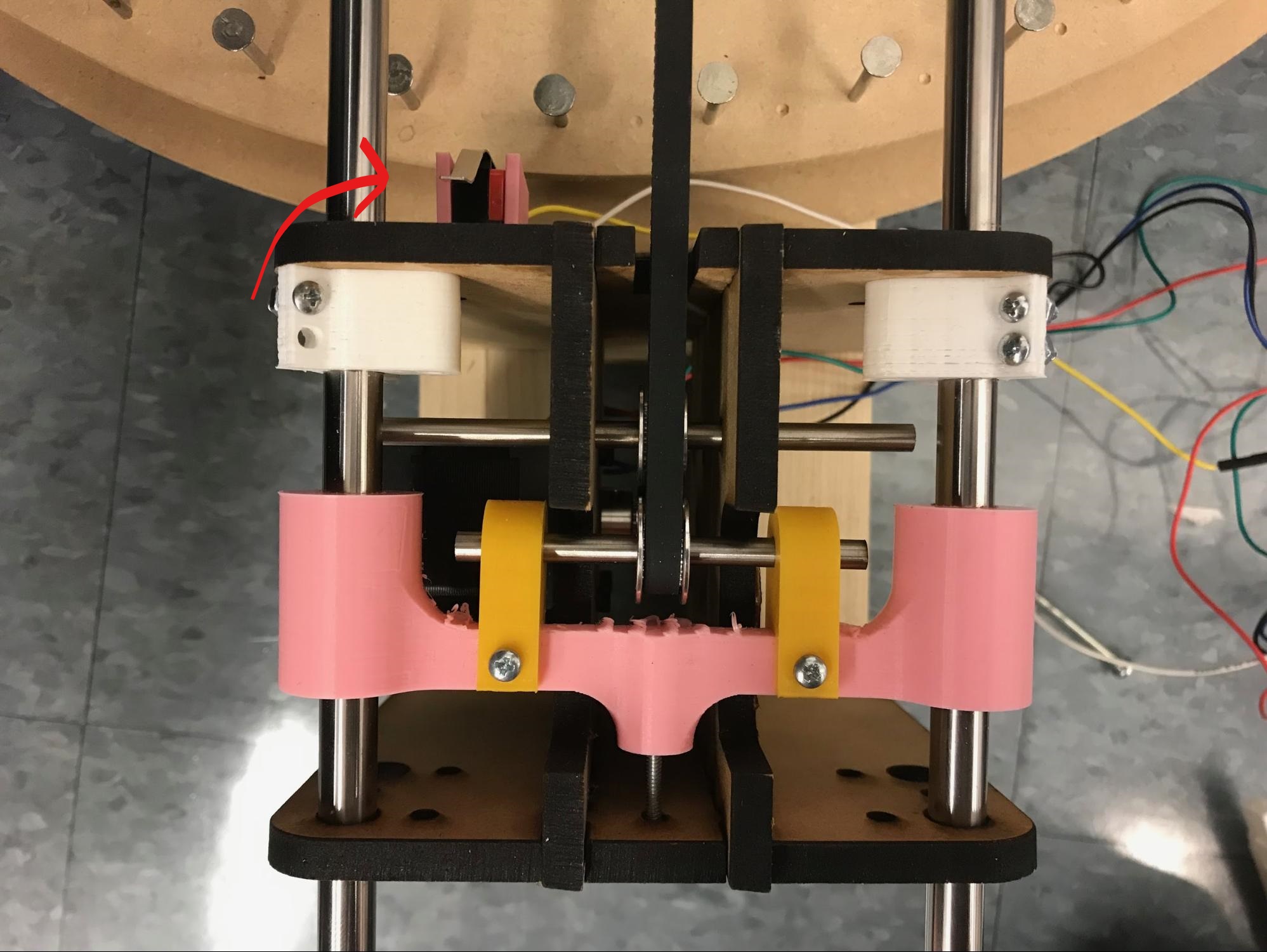
As a reminder, here's what we had at the end of Sprint 2.
Sprint 3 was focused on the refinement and finalization of some of the smaller components of the system. Notably, we developed mounting for the spool and integrated that into our carriage. We also developed mounts for different sensors that we want to integrate into the system, notably a limit switch for homing the radius axis and possibly an infrared sensor for homing the theta axis.
We first set out to add the string placement manipulator. Our idea was to have a nozzle attached to the r-axis manipulator that would have some give so that the nozzle would not get stuck while passing over previously placed string. This was implemented by making the nozzle tip out of shrink tube.
One problem we ran into was the nozzle had too much give and was unable to loop the string around pegs. We remedied this by redesigning the nozzle and using plastic tubing rather than a brittle 3d-printed piece.
This is the new nozzle in action!
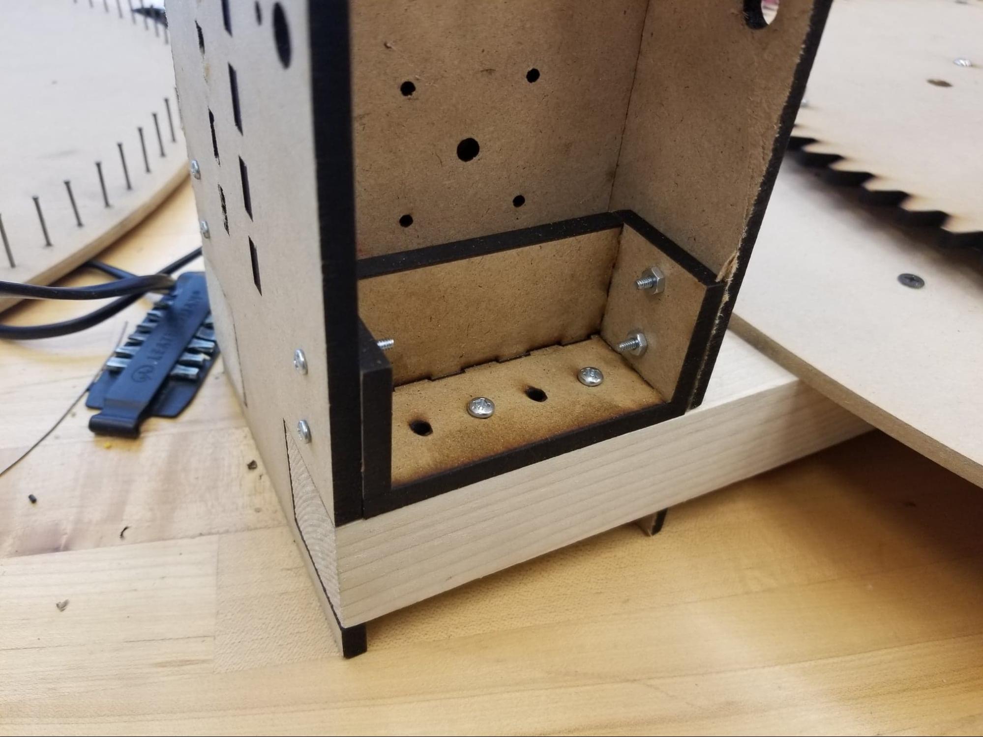
In addition, we also designed and implemented some additional brackets for the gantry. These brackets would keep the plates rigidly mounted to the poplar beams, as well as keep the plates completely parallel to each other. These were added because there were some minor inconsistencies in how the gantry was mounted to the rest of the frame. In general, they helped a lot to reduce slop in the system, and just made everything a lot more rigid and robust.
Next, we added a spool holder to the string manipulator.
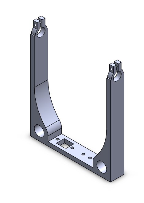
Finally, we 3d printed a limit switch mount for the radius axis as displayed below. A Gikfun V-153-1C25 micro limit switch was used with a digital and ground pin. The digital pin was initiated in the Arduino setup function with the following code statement:
pinMode(R_LIMIT_SWITCH_OUTPUT, INPUT_PULLUP);
where R_LIMIT_SWITCH_OUTPUT corresponds to the digital pin (outputs 0 when pressed and 1 otherwise) and INPUT_PULLUP indicates the pin mode (acts as a pull-up resistor, which inverts the behavior of the input mode).
The SpeedyStepper moveToHomeInMillimeters() function allows us to calibrate our system before each run. moveToHomeInMillimeters() keeps moving in an inputted direction until the limit switch is activated (after which, the ending position is set as the new zero position). In sprint 3, we used the radius limit switch mount to reach the edge of the pegboard before moving to the center and executing the motor commands. This enabled us to consistently start in the same position for every run.
Software
Our team discovered that it was hard to get good recognizeable pictures with a resolution of only 48 pegs on the peg board.
With just 48 pegs, it was difficult for the simulation to create a comprehensible picture of a simple dog.
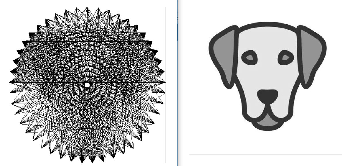
Instead of creating images out of image files, we looked to create cool geometric art based on mathmatical equations. We were impressed with the results.
These designs were made with a sequence where the the string wrapped around peg number n x constant s starting from n = 0.
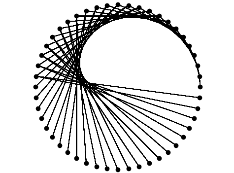
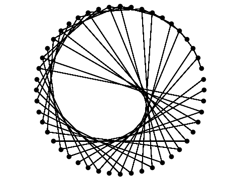
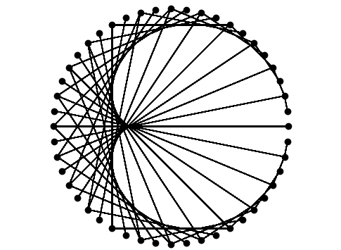
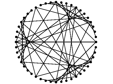
Our team agreed that, not only did these patterns look better than the image-processed designs, but these patterns were a more suitable goal for our MVP. Plus, these designs didn't require 1000+ feet of string!
With this decision, we made some major changes to the code structure.
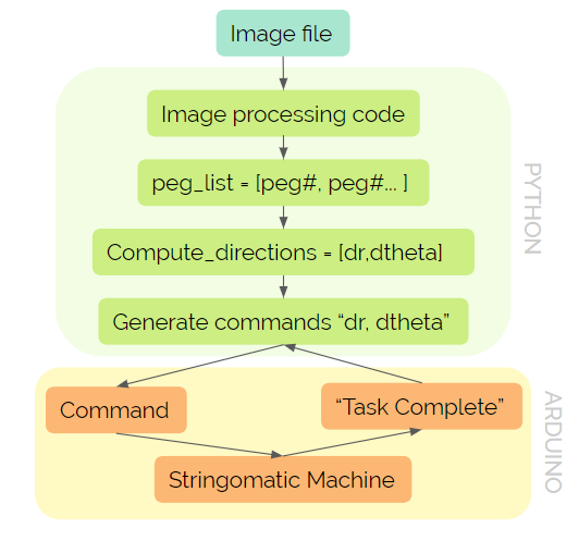
As a reminder, here's what our previous communication architecture looked like between python and Arduino.
As you might have noticed from the images created from the simulation, our pictures no longer require all of the pegs to be connected by a string across the middle of the board. Instead, the machine can loop around the outside of the board to get to its next peg.
In order to account for the wrap around movement, we implemented two movement types for our string dispenser and modified our peg list to include tuples (detailed in the diagram below). A move_type of 1 corresponds to moving across the pegboard. (In sprint 2, everything had a move_type of 1.) A move_type of 0 corresponds to moving around the pegboard.
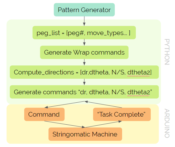
Another noteworthy change in our diagram involves the wrap commands. In sprint 2, the wrap commands were sent one by one for each peg, resulting in significant delay times. To make our system more efficient, we send a series of wrap commands before moving to the first peg. There are two versions of wrap commands (north and south) for each side of the pegboard. When we send our commands, we add an element (‘N’ or ‘S’) indicating which wrap method to use.
Since we introduced move_type relatively late in sprint 3, we decided to modify our computations to work specifically for the cardioid peg list, in which every peg with a move_type of 1 was immediately followed by a peg with a move_type of 0. We wanted to incorporate the move_types without drastically changing our compute_directions code, so we ended up reading in the peg list as pairs of tuples and adding a dtheta2 component to our commands. Every tuple pair contained (1) a peg number with move_type 1 and (2) a peg number with move_type 0. We found dr and dtheta to get to the first peg number using our computations from sprint 2. We then find dtheta2 by calculating the additional rotation needed to move from the first peg number to the second. On the Arduino side, we would break up the string command, move according to dr and dtheta to get to the first peg, use the N/S element to wrap around the peg, and then move by dtheta2 to reach the second peg. While testing, we found that sometimes dtheta2 would undo the wrap around the previous peg, so we decided to wrap around the pegs twice. With these modifications, we were able to move the string dispenser accurately and create a cardioid.
For sprint 4, we want to make our computations more general, so the peg list does not need to be made up of move_type pairs. We would also like to eliminate the double wrapping feature to increase the efficiency of our system.
On the image-processing side of the project, we sought to address the weakness in our pathing algorithm for the string. Our original algorithm computed the line that would cover the most "darkness" in an image starting from the current position of the nozzle. We wrote another algorithm that computed the best line considering all possible start points on the peg board. Unfortunately, this new algorithm did not yield improved results on a peg board of only 48 pegs.
MVP achieved! Check out our Sprint 4 post for more updates!