After pivoting away from the "lighter than air" jellyfish project at the end of the last sprint, Team Adryft leaps head-first into its brand new idea. The five members agreed to keep the team's original name "Adryft" and planned to somehow make it fit the string-art theme if they have time before POE ends...
So, this is what we got done these past two weeks! Boy has it been a sprint.
Hardware
We refined the CAD that was completed at the very end of last week. Besides removing the pegs in the middle of the disk (a decision we made to simplify the stringing process for our MVP), many of the adjustments were small tweaks to make the system fit together better.
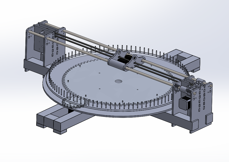
We planned to have our machine powered by two stepper motors. One to move the string manipulator with a belt, and the other to turn a gear to rotate the circular board.
This sprint, the mechanical side of the project ran into many barriers.The largest barrier to manufacturing was cutting the lap joints in the poplar beams that make up the frame of our system. Because none of us were woodshop trained, we had to ask Niyi, one of the woodshop ninjas for assistance. Thankfully, he made time for us, and we were able to cut the beams without much of a problem. The other bottleneck was using the shopbot in order to cut out some of the larger components of the system that wouldn’t fit in the laser cutter.
We also ran into a minor logistical problems. Our amazon order for ⅜” steel shaft was delayed for more than a month. We would not have been able to tolerate this kind of delay because we would have received that critical component well after the end of POE. As such, we were forced to cancel the order and purchase from a different vendor. ⅜” shaft is a very uncommon shaft size, and associated components are much more expensive than components for 8mm, which is the closest metric analog. The original amazon order for ⅜” shaft was extremely cheap, and would have offset the costs of the more specialized components. Having to cancel the order and purchase from a different vendor at full price took a huge chunk out of our total budget. Thankfully, we’ll have enough to still finish the project.
Even though we ran into issues, we got most of the mechanical system fabricated and working this sprint. Because most of the components of the system are made using rapid prototyping techniques, namely laser cutting and 3D printing, we were able to independently make most of the components ourselves. We are getting ready to test and refine the system in the upcoming sprint.
On the electrical side, we first attempted to control one stepper motor with an Arduino Uno and Adafruit Motorshield, but one of the components on the Motorshield was temperature sensitive and turned off when the system got too hot, resulting in a jittering motion. At the time, we did not have any heat sink to place over the component, and another POE team, who had a working stepper motor control system, was working right next to us. After talking with the other members, we decided to follow their recommendation and purchased the OSOYOO 3D printer kit. The 3D printer kit included an Arduino Mega2560, a RAMPS 1.4 Controller (with space for 5 motor drivers), and A4988 stepper motor drivers. We quickly tested out the new electronics and figured out how to control two stepper motors. Even with a few obstacles in the beginning (i.e. thinking we accidentally fried the Mega), the motor control process went very smoothly, allowing us to focus on other things such as calibration.
The RAMPS 1.4 Controller Board:
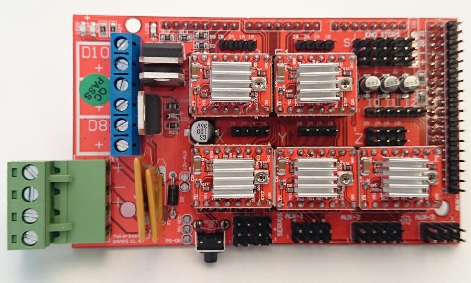
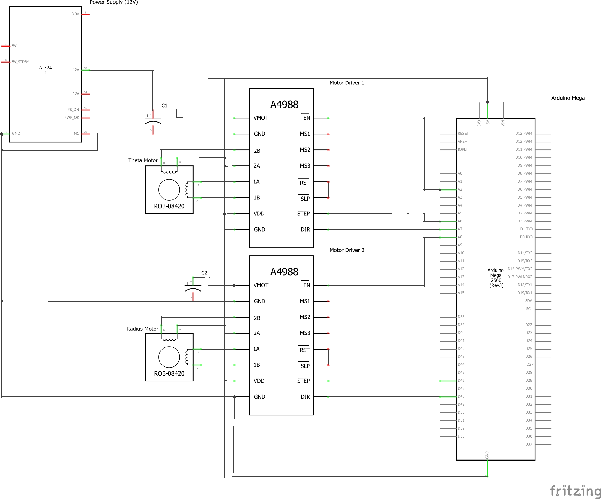
The circuit diagram above details how the stepper motors were connected to the Arduino Mega. The bipolar stepper motors were connected to the A4988 stepper motor drivers via 1A, 1B, 2A, 2B pins. Each driver was connected to the Arduino Mega via the ground, power, enable, stepper, and direction pins. We used a RAMPS 1.4 Controller which we placed on top of the Mega. The Controller allowed us to connect the stepper drivers to our 12V power supply. The capacitor, VMOT, and GND pins were integrated with the Controller.
Software
While trying to control the stepper motors with the Adafruit Motorshield, we used the AccelMotor library. When we switched to the RAMPS 1.4 Controller and A4988 motor drivers, we had to find an alternative stepper control library. After some research, we decided to use the SpeedyStepper library, made by instructor Stan Reifel. SpeedyStepper had very comprehensive documentation and was relatively straightforward to use.
We decided to move the theta motor in terms of revolutions and the radius motor in terms of millimeters. In order to initialize them, we had to find the steps per revolution and steps per mm values. Through some initial experimentation, we found that the theta motor requires 3200 steps to complete one revolution and the radius motor requires 100 steps to move one mm. We did further calibration to verify the gear ratio and to test the accuracy of our radius motor. The expected gear ratio in CAD is 4.64, and after testing we found that 4.69 is a more accurate ratio. We found this by having our theta motor move 4.64 revolutions to see whether the pegboard moved one revolution. While testing the accuracy of the radius motor, we observed that the actual distances were around 1.25 times greater than the expected distances. As a result, we adjusted our 100 steps per mm constant to 80. With calibration, we were able to precisely execute given motor commands.
We also created a string art simulator in Pygame to test our image processing algorithm. The simulator processes a normal image into one drawn by criss-crossing straight lines. This is an example of one of our outputs:
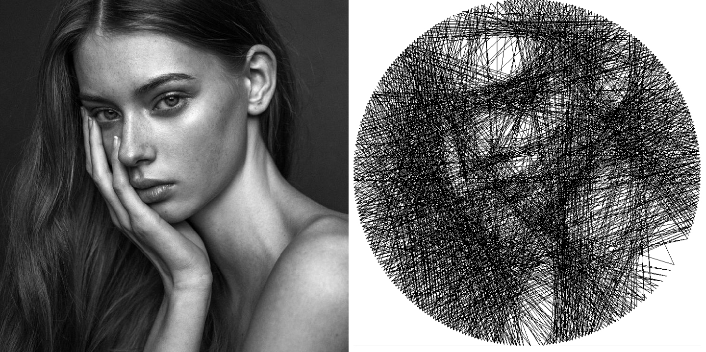
Our image processing is a calculated with a greedy algorithm, which means that every line drawn by the string is the most optimal at that given time. It does not take into consideration what the end picture will look like. For each step, the algorithm draws the line across the board that covers the most "dark" values in the picture.

A problem we ran into was that the algorithm didn't know when to stop. It would keep drawing lines across the board until the virtual length of string ran out.
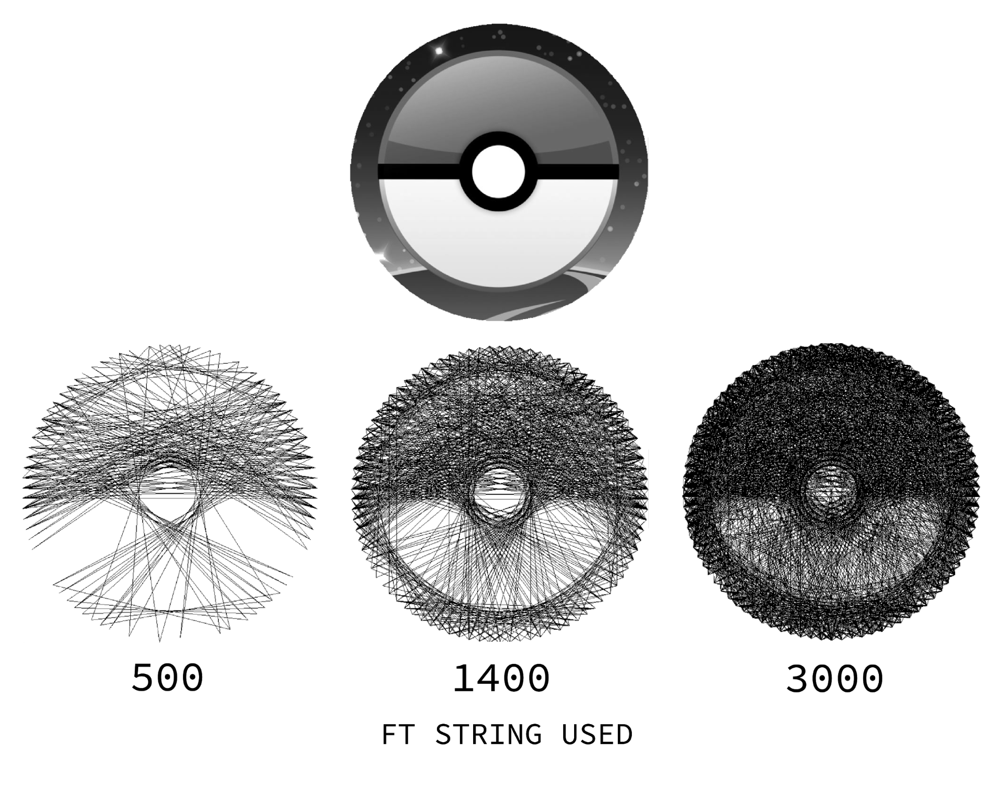
For this pokeball image, the machine should have stopped stringing at about 1400 feet of string. We solved this by creating an algorithm that calculated the error between the drawn image and desired image at every step. It creates a nifty interactive graph like this:
Notice that the error is lowest around 1400 feet of string. It corresponds to the most accurate picture in the figure above!
The image processing algorithm can be found on our Github.