
Besides the firmware, the centerpiece of our project’s software is our “image to string path” algorithm and stringomatic simulator that provides us a GUI to view the paths of the string before testing it on the actual machine.
The image processing algorithm takes an image as an input and returns a path for the string to follow in the form of a list of pegs. The pegs are identified by index n, n = 0 1 2 … (number of pegs on the board).
The Image to String Path Algorithm
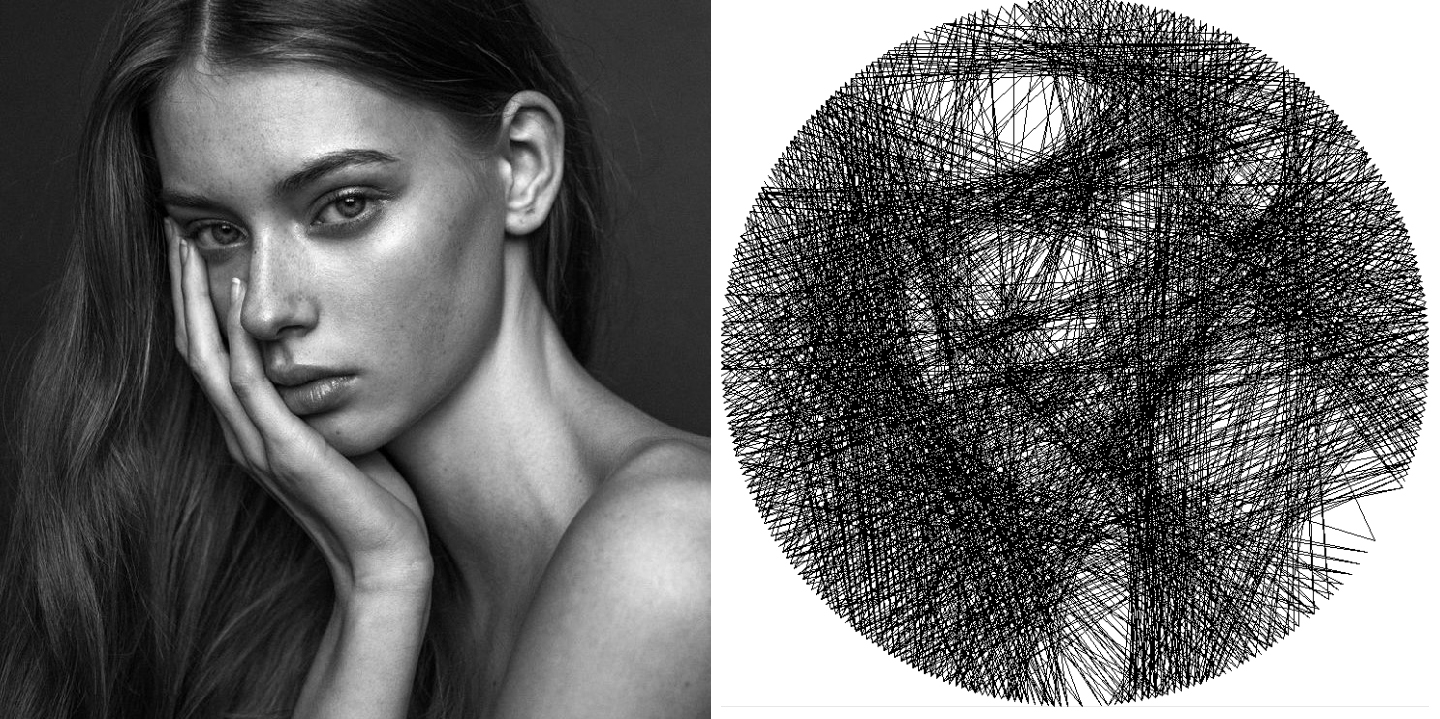
Our image processing is a calculated with a greedy algorithm, which means that every line drawn by the string is the most optimal at that given time. It does not take into consideration what the end picture will look like. For each step, the algorithm draws the line across the board that covers the most "dark" values in the picture.
Notice how the pathing algorithm works on an inverted grayscale picture. This is done so that the pathing always looks for the line that covers the highest sum of grayscale values, as lighter colors correspond to higher numbers.
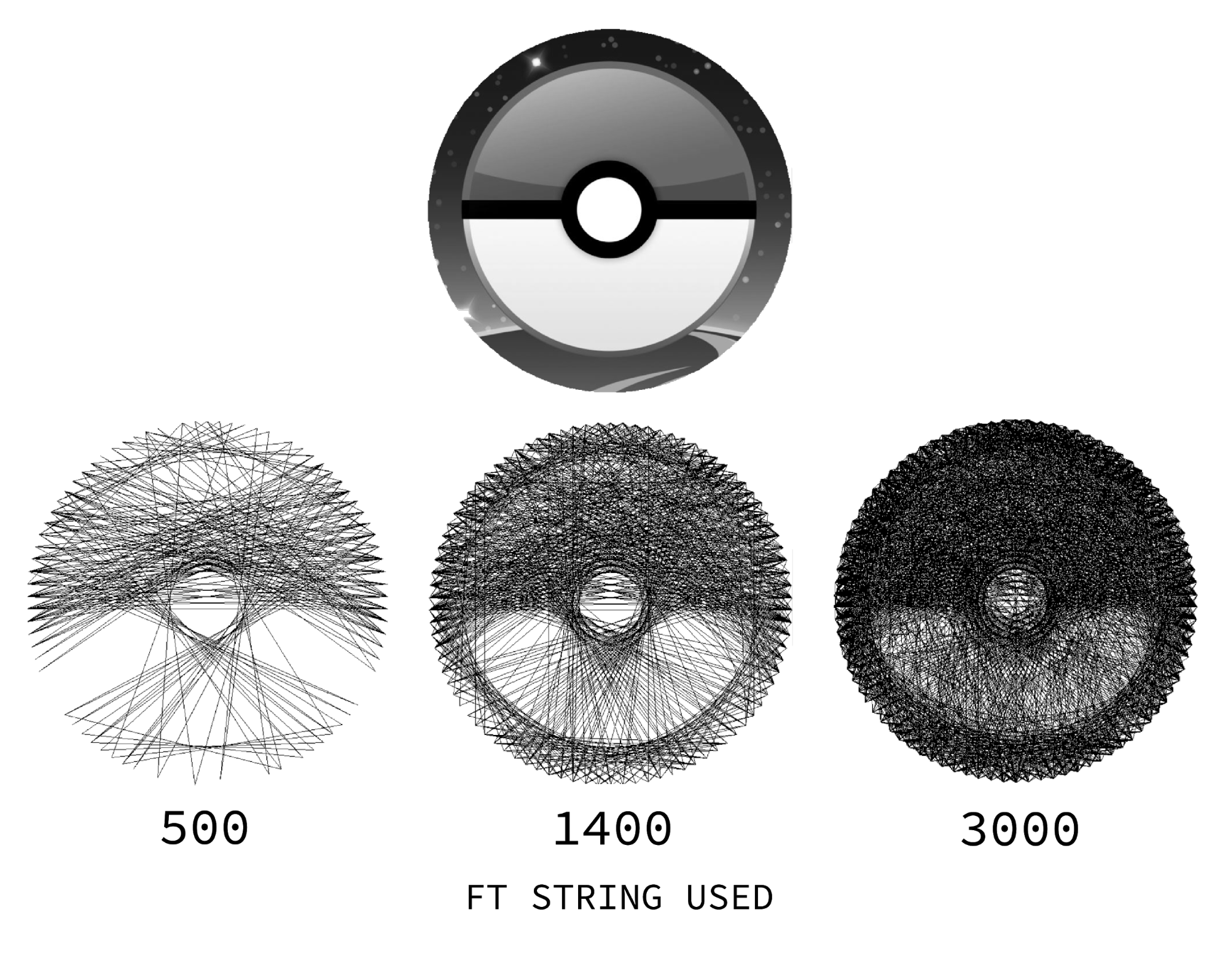
After each step, the image compares the current string drawn picture to the original picture and calculates the error by finding the squared-error sum per each pixel value.
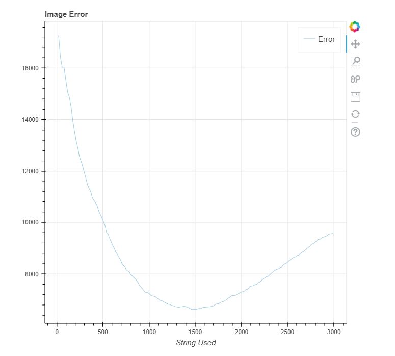
The algorithm stops pathing the string once the error is at a minimum. We see below that the algorithm creates the best result at 1400 ft of string.
This length also corresponds with the lowest error in the graph generated by our simulator code.
Code Structure
The simulation is structured in two main classes. The System class (vaguely named, we know) and the ImageProcessor Class.
The System class runs the GUI for the simulation, and the ImageProcessor computes paths from an image input.
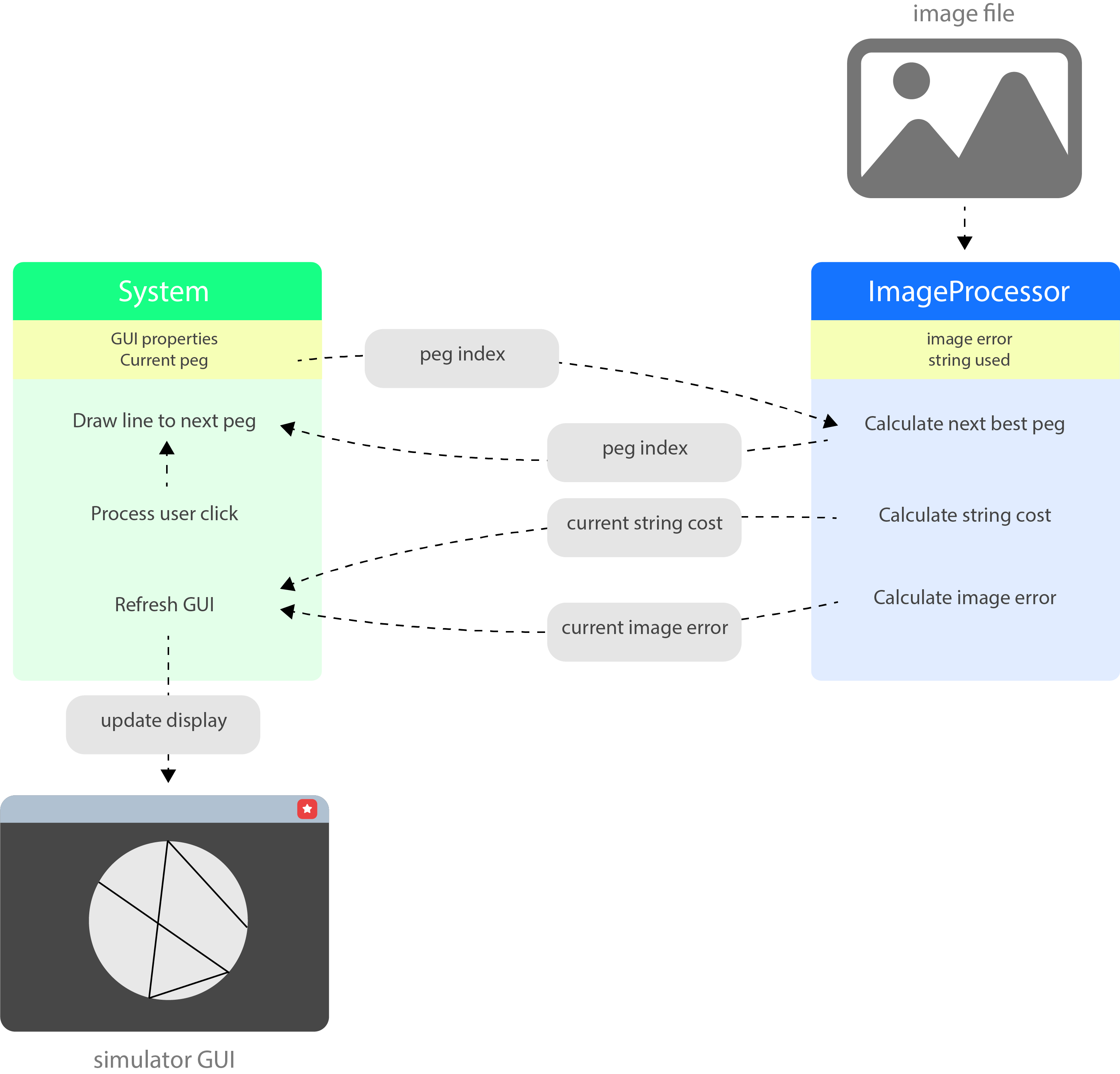
The code shown above is run in a loop where the simulation keeps track of which peg the machine is currently on and the ImageProcessor constantly tells it which peg to jump to next based on the greedy algorithm discussed above.
Code
Take a look at our Github!