
Overview
The gantry moves the wire cutter in the vertical and horizontal direction using two carriages driven by a lead screw-motor coupled system and a belt and pulley system respectively. There are three main components to the gantry:Motor Carriage + Upper Carriage
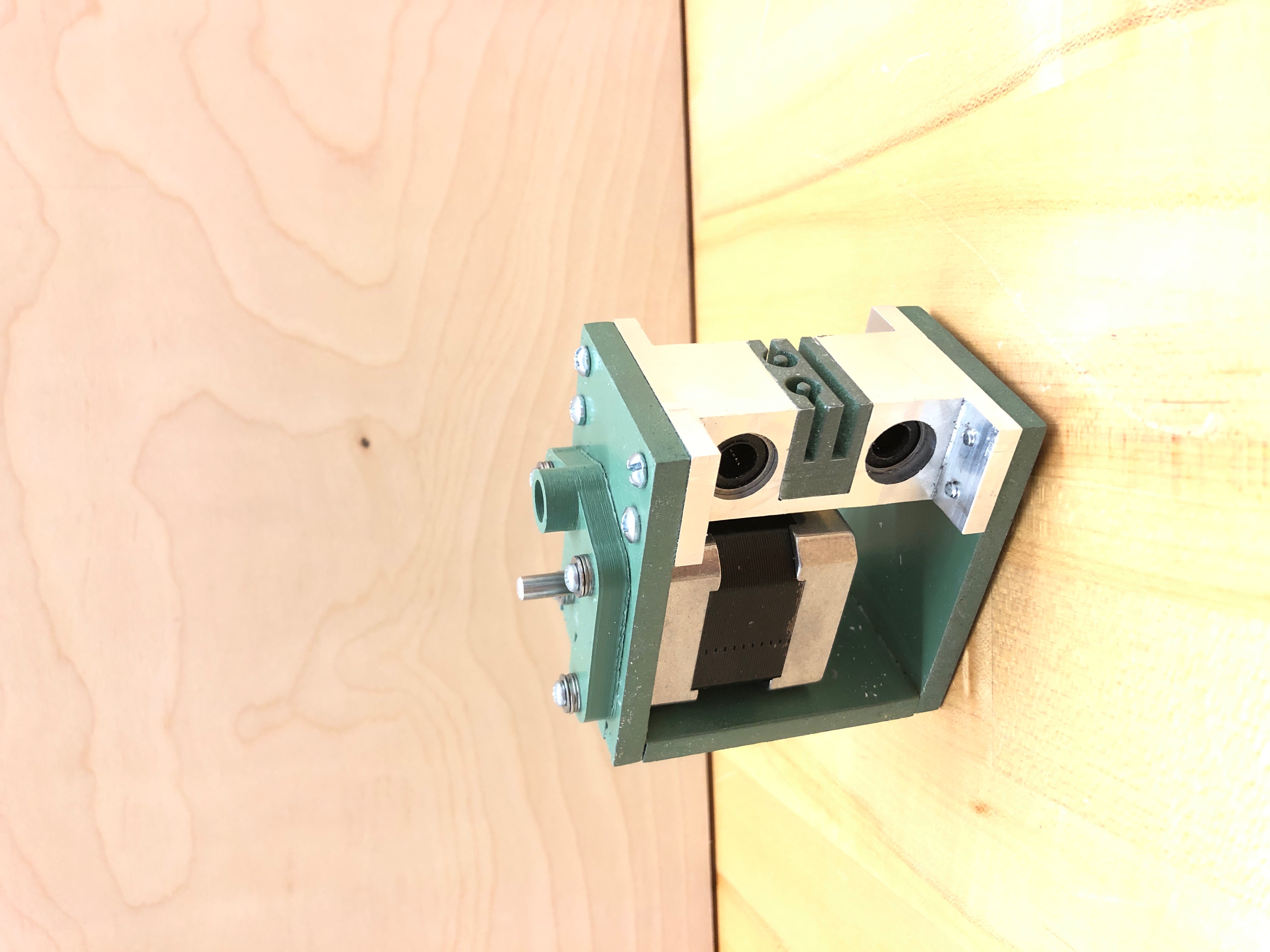
 The motor carriage holds two linear bearings stacked vertically with the belt clamp close to the center of mass to prevent a moment arm from binding the carriage.
The linear bearing housing is CNC milled from aluminum so that there would be less slop.
The motor mount is a 3D printed part that also holds the vertical rail and the lead screw is attached to the motor with a coupler.
Everything is held together with a laser cut MDF structure.
The motor carriage holds two linear bearings stacked vertically with the belt clamp close to the center of mass to prevent a moment arm from binding the carriage.
The linear bearing housing is CNC milled from aluminum so that there would be less slop.
The motor mount is a 3D printed part that also holds the vertical rail and the lead screw is attached to the motor with a coupler.
Everything is held together with a laser cut MDF structure.
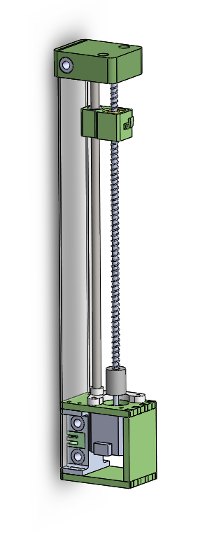
The upper carriage holds the bearing for the lead screw and also holds the guide rail in place to prevent the upright rails from twisting.
This carriage does not have a bearing to prevent over constraining the carriage and therefore binding.
Because the upper carriage and motor carriage needed to always be vertically aligned, we put a piece of acrylic (a rigid piece of material) that attached to both.
Structure
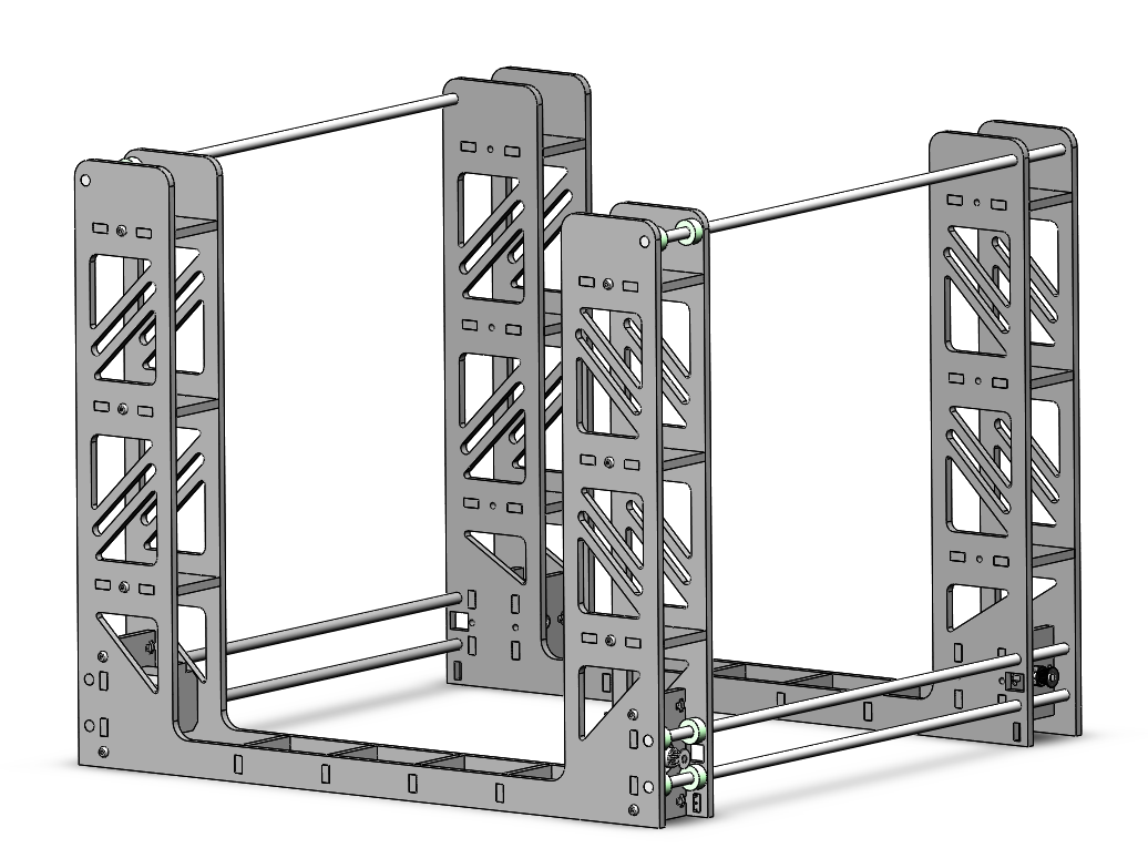
The U-shaped structure is made of ¼” spray painted MDF held together with t-slots and nuts. The panels of the structure sandwich the motor that drive the horizontal motor carriage for a clean look. Each panel is cut out of a single sheet of MDF for structural rigidity and to prevent the need to manually line up the left and right side. The structure has holes for the rails and space for collars to linearly constrain the rails. There is a patterned cut-out throughout the vertical structure for aesthetics.
Wire Carriage
The wire carriage is a 3D printed part that houses a bearing for the guide rail and a copper nut that threads onto the lead screw. There are holes on the carriage for wire routing and a hook that extrudes from the side for the hot wire to hook onto.
Sprint 1
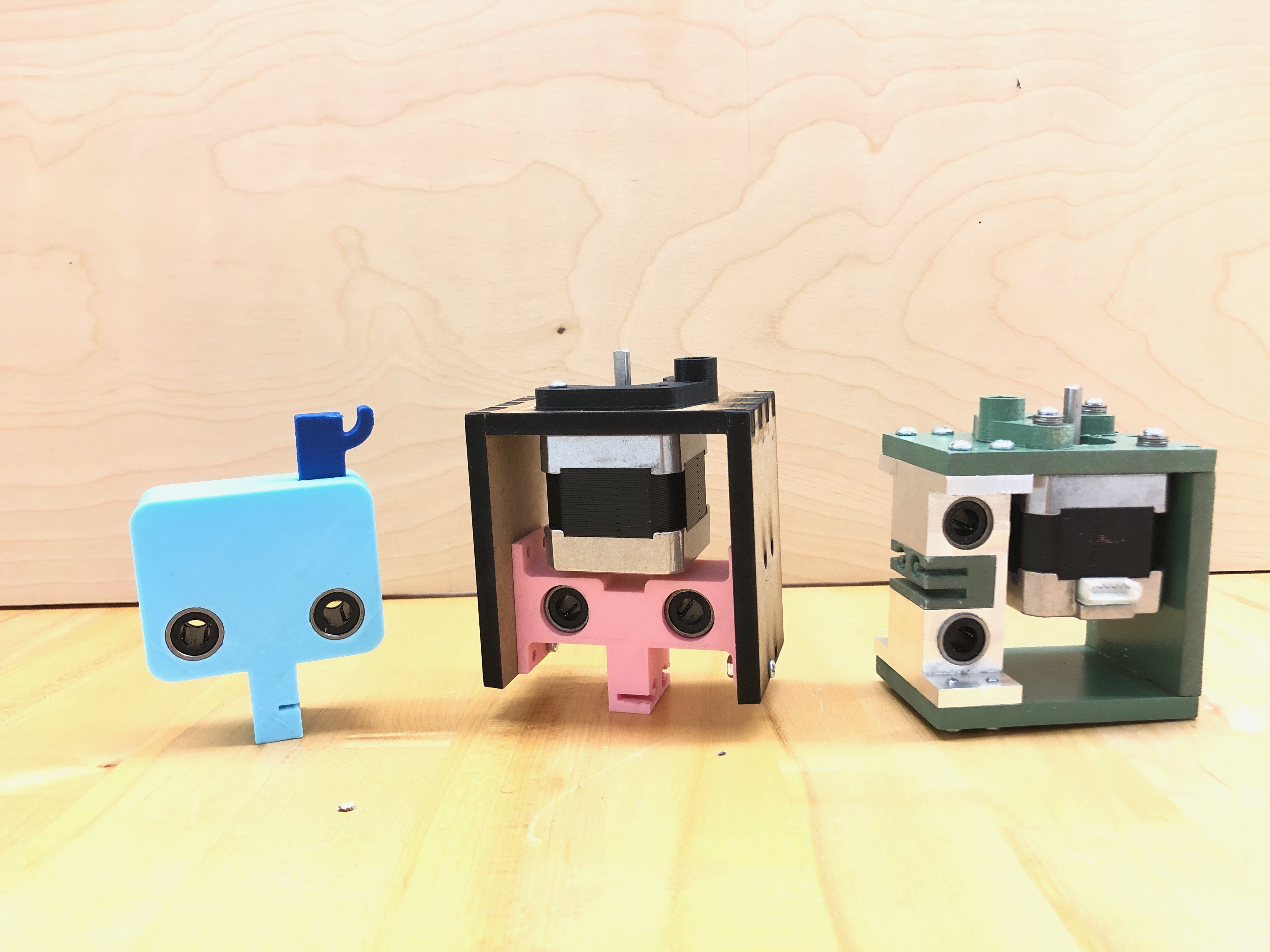
For sprint 1 our priority was to design a simple carriage that could glide across two rails in 1 axis , securely move the wire without snapping or letting it loose, and grip onto the belt drive. We designed a simple carriage where we mounted two linear bearings in parallel and created thin slots on the bottom so that the timing belt can secure into. Additionally, we made a simple hook for the wire so that the springs on the end of the wire can attach onto the hook in easy manner. Though we were able to visualize and produce physical products of our concepts, we found several difficulties while manufacturing this carriage because of the lack of tolerance of the 3D printers. Based on our process, we learned that 3D printers have unreliable tolerances, and that we should be more careful when setting up critical dimensions in CAD for the 3D printers.
Sprint 2
For sprint 2 our priority was to integrate stepper motor that controlled the z-axis position of the wire and create additional carriages to accommodate the movement of the wire across z axis and increased height of the overall carriage assembly.
We designed separate wire carriage that held the wire and upper rail carriage that supported the balance of overall carriage.
Though we were successfully able to glide the wire across 2 axes, we found other design flaws.
The upper rail carriage would not perfectly glide along with the base rail carriage, which delayed the movement of the overall carriage.
Additionally, despite our consideration on the tolerances of 3d printers, we still had hard time mounting the linear bearings onto the carriage, so we ended up using tape to securely fit the linear bearings.
From this sprint, we learned that the lower rail carriage should be fabricated from the metal, which allowed us to have tighter tolerances than the 3D printers allowed.
Furthermore, we decided to think of better idea to align and position the three rails that held the carriage to prevent delays in carriage motion.
Additionally, we designed our preliminary frame made out of ⅛” hardboard and the base out of ½” plywood.
Unfortunately, this material easily flexed, which made the overall gantry not sturdy.
We decided to search for thicker material that will make the gantry more sturdy.
Additionally, we learned that we should design for manufacturing so that when we actually assemble this gantry, it is easy to access screws or slots necessary for crucial components.
Also, we found out the base for the part was way too low, which limited the range of cut for the hot wire.
We decided to modify the base so that the base is about the same height as the lowest point of the wire carriage.
Sprint 3
For sprint 3 our priority was to solidify our CAD so that when we manufacture the carriage, we know for certain that the carriage will work.
Rather than triangulating the positions of the rail, we aligned the positions of the rail vertically to make the sliding of the carriage easier.
Additionally, we moved the position of the timing belt higher so that it is closer to the center of mass of the lower carriage.
We decided that the lower carriage would be made out of aluminum so that we can manufacture with tighter tolerances, which will allow linear bearings to be fit more snugly.
Furthermore, we redesigned the frame so that the frame is made out of ¼” MDF, which would make the gantry more sturdy.
We also decided to integrate the base onto the enclosure so that when the vice is assembled onto the enclosure, the wire can reach close to the vice base plate.
Final Product
Our final gantry was made out of carriages fabricated from both 3D printer filament and aluminum stock, along with frame made out of ¼” MDF.