Servo Motors
In order to move the Stewart platform and provide haptic feedback, there must be actuators on the platform's arms. However, most types of actuator would not be suitable for the task. Open-loop motors such as stepper motors would not be able to detect the user's motions, and normal closed-loop motors such as hobby servomotors would not be compliant enough for the user to push the platform. We therefore decided to build our own servomotors.
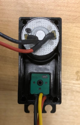
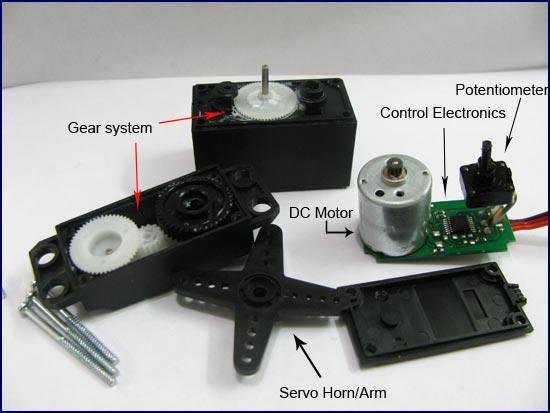
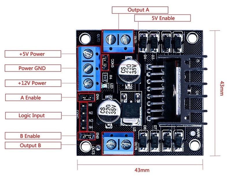
Building smooth, durable servos is usually difficult and expensive. Precise gears are expensive, and motors that can exert continuous torque without overheating are rare. Therefore, instead of starting from scratch, we bought six hobby servos and turned them into custom servomotors with the features we needed. We removed the electronics, leaving only the motors, geartrains, and encoders. We connected the motors to three double-H-bridge brushed motor drivers. The encoders are simple analog potentiometers, so we wired them directly to the control board. The control board is a Teensy 3.2 microcontroller board, with enough I/O pins to drive all six motors and read from all six potentiometers.
The motors are driven with PID control loops, taking feedback from the encoders to correct their positions. The PID control algorithm is a common algorithm used when speed and precision are important, and when feedback is available. The Teensy has enough processing power to run six PID loops in parallel, while maintaining steady communication with the computer.