Electrical
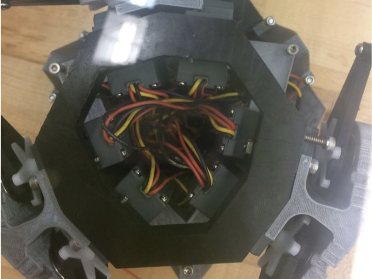
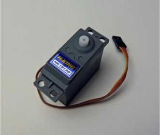
The electrical system is comprised of a Teensy 3.2 that controls 6 servos via 3 dual h-bridge motor controllers. In order to individually control the servo motors, the internal wiring needed to be modified (more information on modifying the servos can be found here). The potentiometers and DC motors were separated from the internal servo chip and rewired to the Teensy and motor controllers, respectively. We used a Teensy controller because of the abundance of PWM, digital and analog pins. The Teensy powered and read from each of the six potentiometers to read servo positions.
The Teensy 3.2 works very similarly to the Arduino micro controller. The same IDE can be used to program it and the Teensy uses the same language. To use Teensy with the Arduino IDE, you must install the Teensy add-on package. It is a free download here. You will also need a mini usb cable to connect the Teensy to your computer. Once the add-on is downloaded, the Teensy boards will appear as options to compile for. Depending on the Teensy bought, you may also need to solder pin headers to the board. We used straight pin headers for the hole ports on the top of the board and used L shaped pin headers for the surface mount ports on the back of the board.
The DC motors within the servos were connected directly to the h-bridge motor controllers. Each of the motors on the motor controller was controlled by the Teensy via 2 digital pins to control direction and one PWM pin to control speed. The Teensy and thus potentiometers were powered by computer USB for interaction with the game. The servo motors were powered via 4 AA batteries for 6V of power. Ground from the Teensy also needed to be wired to the battery pack to avoid interference. We also incorporated one push button to allow for interaction with the game. This button required connection to ground as well as a digital pin on the Teensy to read clicks.
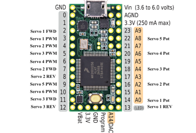
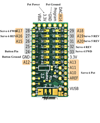
Below you will see a complete pin out diagram that shows which pins on the Teensy 3.2 we used as well as what they were used for. Additionally, there is a power diagram and a data diagram of our completed system.
The Teensy 3.2 works very similarly to the Arduino micro controller. The same IDE can be used to program it and the Teensy uses the same language. To use Teensy with the Arduino IDE, you must install the Teensy add-on package. It is a free download here. You will also need a mini usb cable to connect the Teensy to your computer. Once the add-on is downloaded, the Teensy boards will appear as options to compile for. Depending on the Teensy bought, you may also need to solder pin headers to the board. We used straight pin headers for the hole ports on the top of the board and used L shaped pin headers for the surface mount ports on the back of the board.
The DC motors within the servos were connected directly to the h-bridge motor controllers. Each of the motors on the motor controller was controlled by the Teensy via 2 digital pins to control direction and one PWM pin to control speed. The Teensy and thus potentiometers were powered by computer USB for interaction with the game. The servo motors were powered via 4 AA batteries for 6V of power. Ground from the Teensy also needed to be wired to the battery pack to avoid interference. We also incorporated one push button to allow for interaction with the game. This button required connection to ground as well as a digital pin on the Teensy to read clicks.
Below you will see a complete pin out diagram that shows which pins on the Teensy 3.2 we used as well as what they were used for. Additionally, there is a power diagram and a data diagram of our completed system.
Materials
- Teensy 3.2
- 6 HK 15138 hobby servo
- 3 L298N dual H-bridge motor driver
|
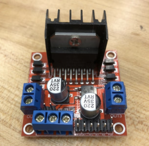
L298N Motor Driver
|
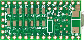
PinOut
|
|
Button
|
|
Power Diagram
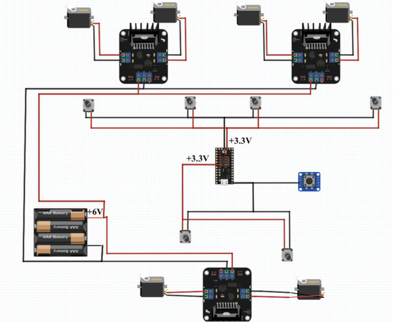
Power diagram of completed electrical system
Data Diagram
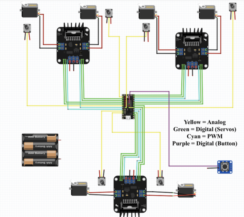
Data diagram of completed electrical system