Mechanical
Executive Summary
|
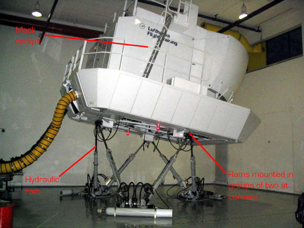
A Stewart platform allows one to position a table above a base so that, with a stationary base, the platform can be moved in all six degrees of freedom: up-down, left-right, forwards-backwards, pitch, roll and yaw. Stewart platforms are used commercially in flight simulators. The pilot, in a mock cockpit, sits on top of the platform and can feel motion in all six degrees of freedom. Six hydraulic rams run from the corners of the platform to the corners of the table, as seen alongside.
|
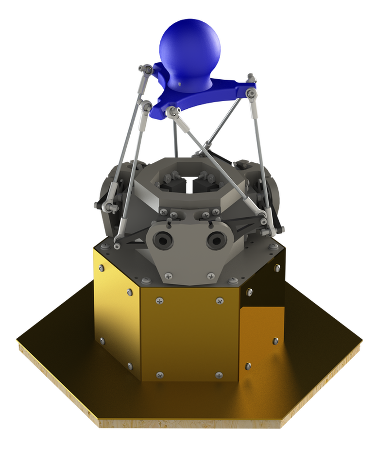
We reasoned that, if the table of a Stewart platform can be directed to move to specific positions with specific rotation, a free-floating platform, moved by hand would make an excellent computer input device.
Most commercial Stewart platforms use hydraulic rams as pushrods to hold the platform up. The platform is moved by changing the lengths of the pushrods. Since linear actuators (whether hydraulic or electric) are expensive, we used fixed-length pushrods made of 1/8-inch steel rod stock, supported at the bottom by a 3D printed crank. Changing the crank’s position has the same effect as lengthening and shortening the pushrods in a hydraulic Stewart platform. We threaded both ends of the pushrods, and screwed rod-end ball joints to them.
Most commercial Stewart platforms use hydraulic rams as pushrods to hold the platform up. The platform is moved by changing the lengths of the pushrods. Since linear actuators (whether hydraulic or electric) are expensive, we used fixed-length pushrods made of 1/8-inch steel rod stock, supported at the bottom by a 3D printed crank. Changing the crank’s position has the same effect as lengthening and shortening the pushrods in a hydraulic Stewart platform. We threaded both ends of the pushrods, and screwed rod-end ball joints to them.
We decided to mount the cranks to hobby servos. A servo uses a variable resistor to detect the position of its servo horn. If the servo horn is found to be in a different position to the desired position, the servo’s inbuilt motor driver runs a geared-down brushed electric motor in one direction or the other to move the horn to the desired position. We removed the motor drivers from our servos, and soldered manually to their built-in variable resistors. This allowed us (rather than the servo’s inbuilt motor driver) to read the arm’s position. We left the gears and motor in place. These give some resistance to platform movement, allowing it to stay in place when let go. We also use the servos for force-feedback. In the game we built to demonstrate the Stewart platform, force feedback kicks in when the player hits another object or a wall.
Structure
|
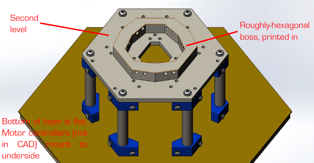
Most of the intricate parts were 3D printed out of PLA on the Original Prusa i3s all of our STL files can be found here. A few design decisions were made to make 3D printing easier. The second level was originally designed with a hexagonal ring on the top to mount servos, and several studs on the bottom, to allow the motor controllers to stand off of the layer. Since printing a flat plate with bosses on both sides would require a great deal of support material (no matter if printed upside-down or right-side-up), we decided to use delrin spacers instead of printed-in studs.
|
|
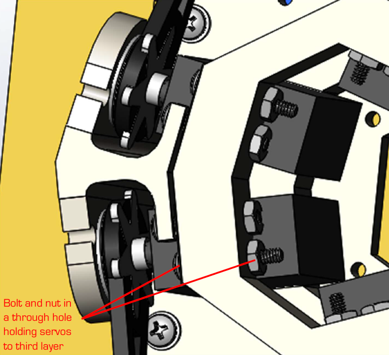
Screwing directly into 3D-printed parts with wood screws or similar is an unreliable fastening method. Screws cannot be inserted and removed for debugging more than once, because the screwing the screw in at first irreparably widens the hole. In some places, we replaced blind holes with through holes and used a bolt and a nut.
|
|
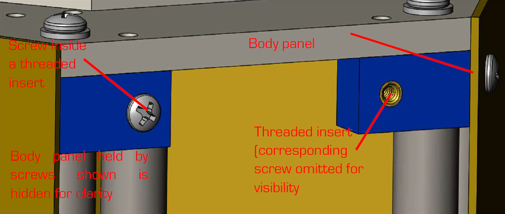
In places where using a through hole would be too limiting to our design, we printed blind holes and used copper-alloy threaded inserts with a knurled outer surface. We heated these up with a soldering iron, and then pressed them into holes printed into the parts. The holes were printed slightly small, so that the plastic would melt tightly around the insert. We can now screw screws into and out of the threaded inserts as often as necessary, since hole wear and widening is no longer a problem. We had some problems with the insert drifting sideways while pressing them in, since they were sufficiently hot to melt sideways through the plastic. Our skill at pressing in inserts improved with practice, however, and drift proved not to be a problem on our final build.
|
|
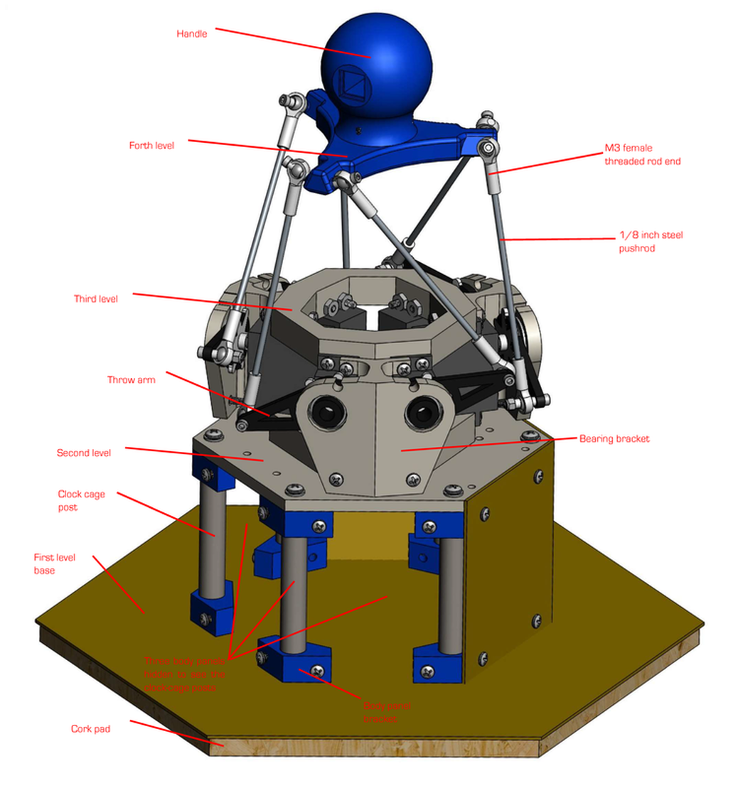
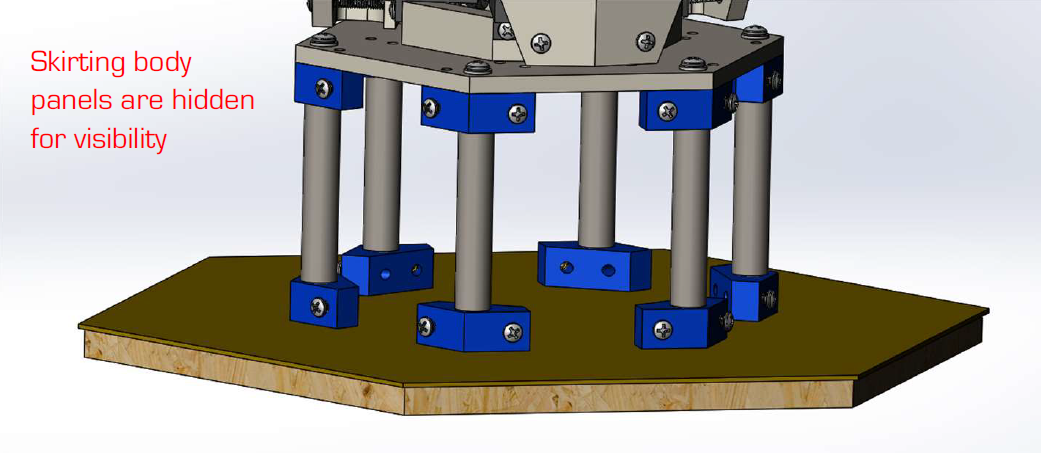
The second level of the mouse rests 9cm above the base. It is held there by 6 clock cage posts, one at each corner of the hexagon. Clock-cage posts were made out of ½-inch hot-rolled steel rod stock. Aluminum would have been more than strong enough, but we chose steel because it is heavier, and allows us to build a more bottom-heavy mouse. We cut the posts long on the horizontal band saw. The posts were then faced down to within 0.005 inches of their nominal length on the lathe. Also using the lathe, we center drilled, drilled and tapped (using a manual tap wrench) holes at both ends of the posts to accept 8-32 screws. We drilled the holes deeper than necessary, that way we did not need to use a bottoming tap.
|
Below one can find .stl files of our 3D printed parts.
Body Panels and Base
Body panels are 1/16-inch copper-alloy sheet that we sandblasted to improve surface finish and remove tarnish. Copper-alloy sheet was chosen for its density. It allows us to have a very bottom-heavy mouse that does not tip over, even with aggressive use. Sheet-metal flat patterns were printed out on paper, and these were glued to one face of the sheet metal with spray adhesive. We cut along the lines of the patterns with sheet metal tools (angle shears and jump shears). Holes were also marked on the pattern. We made a dent in the metal at each whole location with a punch and hammer, and then drilled at each hole with the drill press. Since thin stock such as this can grab on the drill bit and rotate with it, creating a safety hazard (this is why holes in thin stock are normally made on the turret punch), we were sure to clamp it firmly to the drill press table, and take light “pecking” cuts with the drill bit. After shearing and drilling, we abraded away the paper and adhesive with a manual grinder running a wire brush wheel. The sheet metal was again clamped down firmly, this time to the workbench, lest the grinder toss it sideways. We followed this up with sandblasting, which gave the copper-alloy a matte surface finish, and removed any leftover adhesive. We 3D printed body-panel brackets that slid onto the clock-cage posts. Body panels were screwed into holes (with threaded inserts) in the brackets to the sides with ¼-inch long 6-32 screws. We glued a layer of laser-cut cork to the bottom of the base to prevent the mouse from slipping across the table with aggressive use. Since the laser-cutter left a residue of foul-smelling ash, we painted over the cut edges with PVA, the raw material used in acrylic paint.
Throw Arms
We needed a fair amount of trial and error go get the lengths of the servo arms right. Too short of an arm length gives our mouse poor range of motion at the handle which is not ideal. Since the servos each consist of a brushed electric motor that is geared down, turning the servo arm through a small angle forces the motor to make several revolutions. Because of this, the servos need a fair amount of torque to be backdriven, even when their motors are off. The shorter the throw arm, the more force needs to be applied to the handle to provide sufficient torque backdrive the motors. Too long of an arm gives excellent range of motion at the handle, but reduces the force the motors can provide when giving force feedback. If the motors are not torquey enough to stop the user’s hand when, for instance, their character hits a wall, force feedback is not convincing.
|
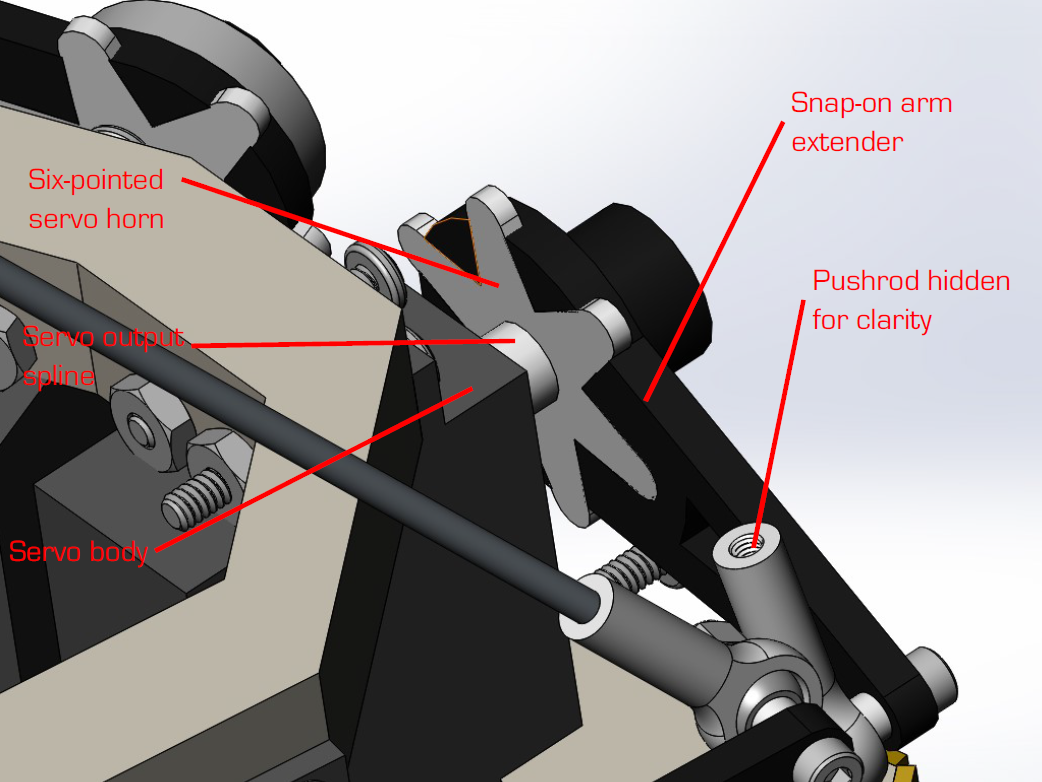
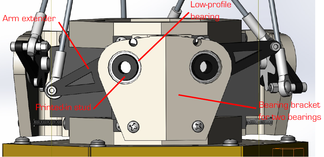
We needed a fair amount of trial and error to get the throw arm length right. We ended up choosing an arm length that was longer than any of the standard servo horns, so we needed to print an arm extension to mount to a standard horn. We chose a six-pointed servo horn because it would have a large contact area with our arm extender.
Our arm extender snaps onto the six-pointed servo horn, which is in turn screwed to the spline on the servo’s output. Using a screw to attach the horn to the spline is standard among the remote-control hobbyists who usually use the servos, but adding arm extenders is not. |
|
To avoid loading the servo output spline (and the internal bushings behind it) in bending, we printed a stud into the outside face of each arm extender. Each stud is pressed into the inner race of a ball-bearing, and the outer races of the bearings are held in place with brackets designed expressly for that purpose. One bracket serves to hold the bearings for two servos, so only three brackets total are needed.
|
Pushrods
Pushrods were made out of 1/8-inch steel rod stock, threaded at both ends with a die. Since the rods were too small in diameter to face to length on the lathe, and also too small in diameter to safely band saw, we cut them long by hand with diagonal wire cutters. We then disk-sanded them down t length, frequently checking their length with a pair of calipers. We periodically dipped the ends in cutting oil to prevent excessive heat and work-hardening, which would make later threading difficult. Pushrods were then chucked into the lathe, and threaded at both ends with an M3 die in a diestock. The lathe’s motor was not needed, but the tailstock and drill chuck were used to line up the die. The 1/8-inch steel was slightly larger in diameter than the 3mm stock that would have been ideal, but the die easily removed the extra.
We initially tried using 3mm aluminum rod (reasoning that it would be easier to thread) but this bent if the mouse was not used gently. The steel proved easy to thread, even with a short-handled diestock; tapping fluid was used, however. Aluminum rod end ball joints were screwed onto both ends of each pushrod. With 6 pushrods, 12 rod ends were needed. Rod ends had a female M3 threaded shank, and a 3mm diameter hole in their ball, through which a M3 bolt fit with no perceivable slop.
We initially tried using 3mm aluminum rod (reasoning that it would be easier to thread) but this bent if the mouse was not used gently. The steel proved easy to thread, even with a short-handled diestock; tapping fluid was used, however. Aluminum rod end ball joints were screwed onto both ends of each pushrod. With 6 pushrods, 12 rod ends were needed. Rod ends had a female M3 threaded shank, and a 3mm diameter hole in their ball, through which a M3 bolt fit with no perceivable slop.
